Lattice Deform Rig Component in Houdini APEX
Recently, I've been doing a lot of R&D with APEX, specifically with APEX Script, which has been a joy to use, despite it taking a little getting used to. One of the things I needed to use Apex Script for was implementing a lattice deformer in one of my rigs.
Among many other quality-of-life improvements to APEX, Houdini 21 also introduces the new Lattice 2.0 APEX node. However, there wasn't too much information to find on how to use this new APEX node. This little post is my attempt at filling that gap.
I've developed a custom Rig Component written in APEX Script that I hope will help simplify implementing a lattice deformer into your rig. It does require a little bit of prep, but I hope you'll find it a pretty approachable workflow.
First, I'll cover how to use my custom Rig Component, and afterwards, I'll break down the code for those interested in learning a bit of APEX Script. Please keep in mind I still have plenty to learn in terms of APEX Script, so I'm sure there are ways to optimize this component. If you have any suggestions, I would love to know!
I'll base my setup on a simple little pillow APEX Rig I've created. If you'd like to skip ahead, you can also download the full scene file directly from Gumroad (it's free to download) here.
Lattice Rig Component
How to use the Lattice Rig Component.
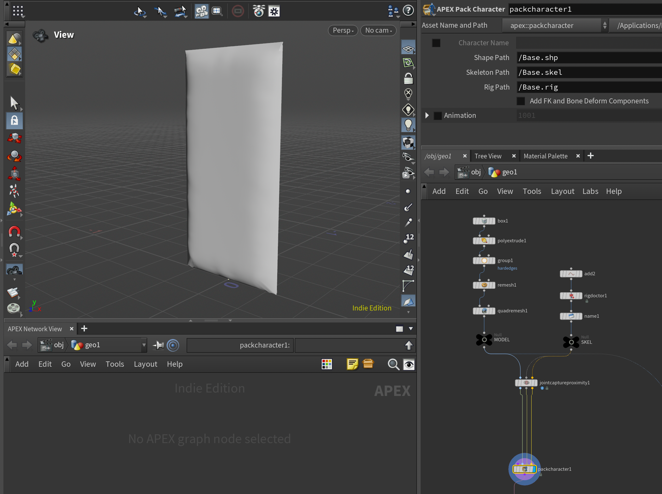
Step 1: Pack Character
The first step to setting up our lattice deformer is to pack our character so it's ready for APEX. I'm not going to go into depth about that in this tutorial, but you can download the project file for free from here and take a look yourself, or read my older post about the basics of rigging in APEX here:
My pillow rig consists of a single control called root, placed at origin, and bound to the pillow mesh using a Joint Capture Proximity SOP. I've then piped the 3 outputs of the Joint Capture Proximity SOP into the new Pack Character node (this is a new simplified way of packing a character for APEX rigging).
Step 2: Prepare Lattice
Following that, before we start rigging, we need to add a few more elements into our character folder. This will be our LATTICE and our LATTICE CONTROLS. The lattice is the lattice mesh itself, and the lattice controls are the joints/points we want to use to deform the lattice.
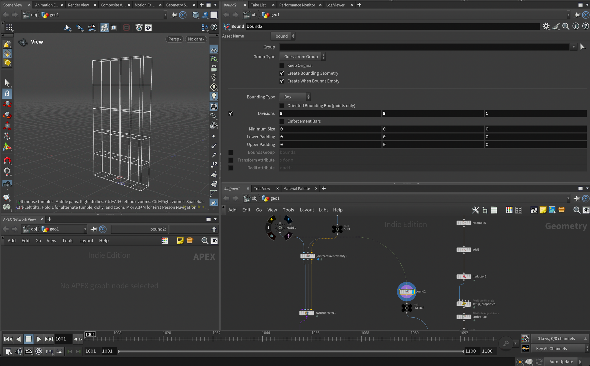
The easiest way to set up a lattice mesh in Houdini is using the Bound node and enabling Divisions. This will create a lattice grid similar to what you might see in its Maya-equivalent. You can use however many divisions you like. In my case I used 5x5x1.
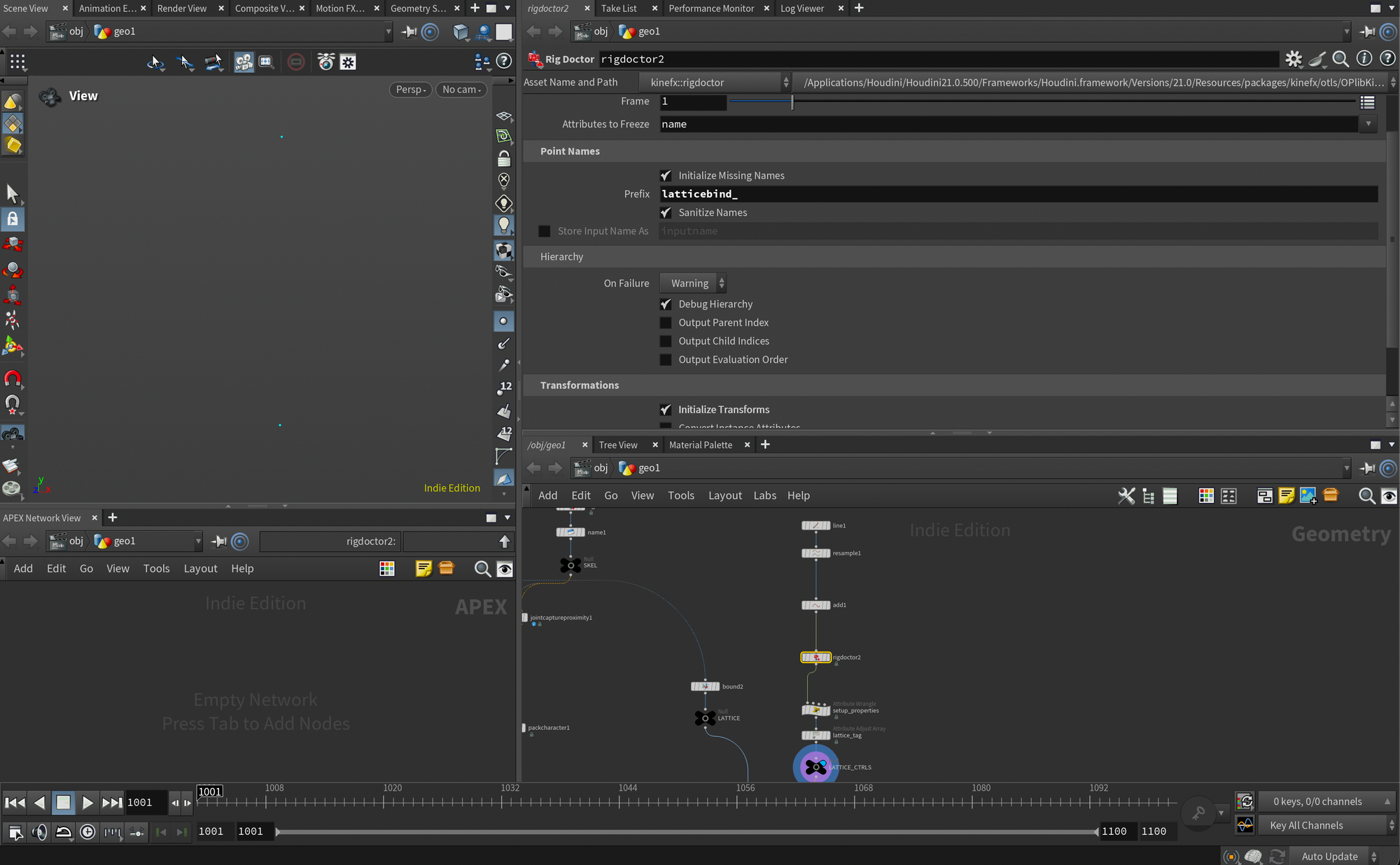
For the lattice controls I created two points at opposite ends of the lattice. It's up to you how you want to add them. After creating the points I turned them into proper joints by adding the Rig Doctor node and turning on Initialize Transforms. Also note I set the prefix of the joints to lattice bind_ in the Rig Doctor.
This is where we need to prep a few things specifically for my lattice deformer rig component. The Lattice 2.0 node in APEX needs to know how many Divisions your lattice has. The simplest way to do this, in my opinion, is to store it directly on the lattice controls. That way, if you have multiple lattices in your rig, you won't need to manually enter what divisions you ended up using.
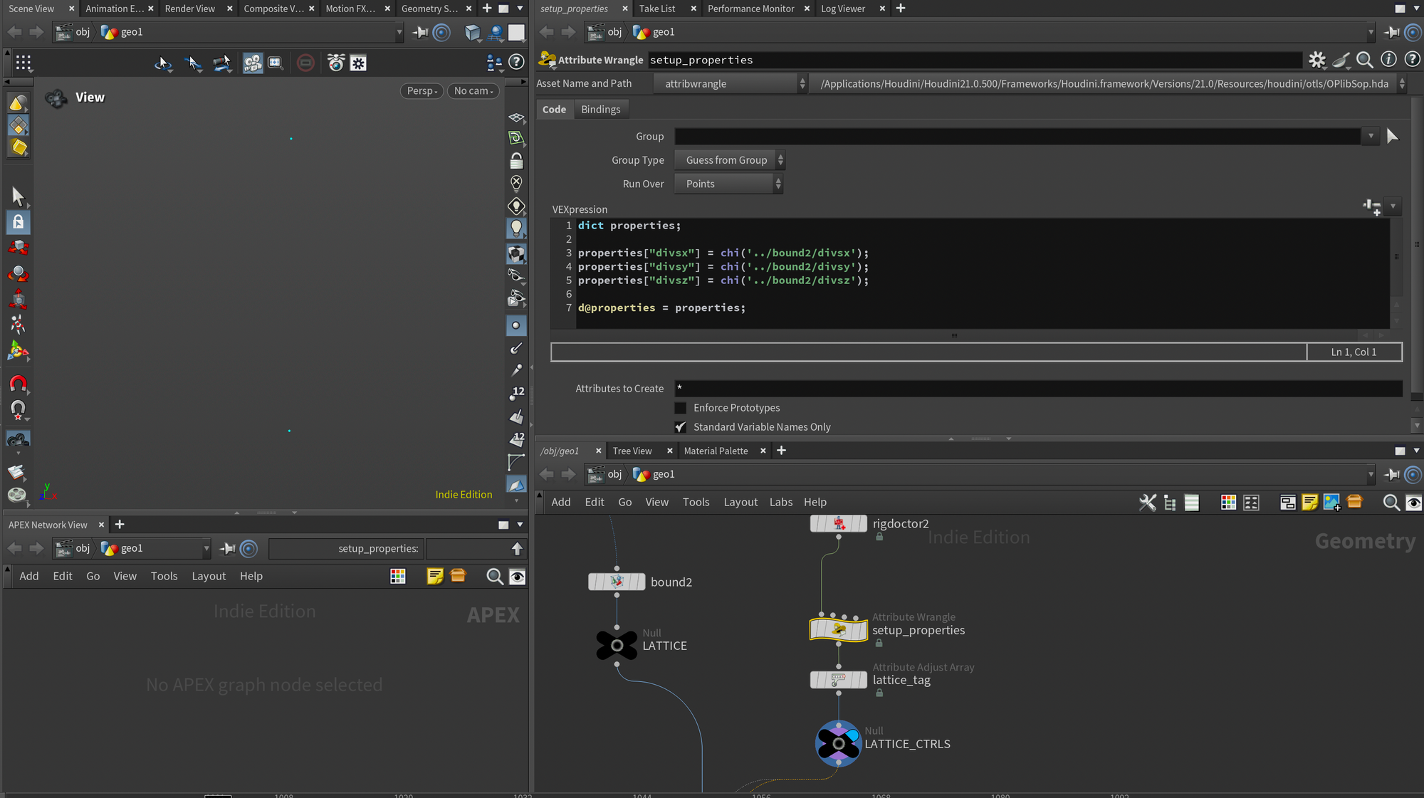
I personally found that the nicest way to store this information was to use the special APEX dictionary called properties. The wrangle below pulls the division values directly from the Bound node and adds them as dictionary elements corresponding to each axis.. Only thing you may need to change is the chi('../bound2/divsx') part of the script, as this needs to point to your Bound node.
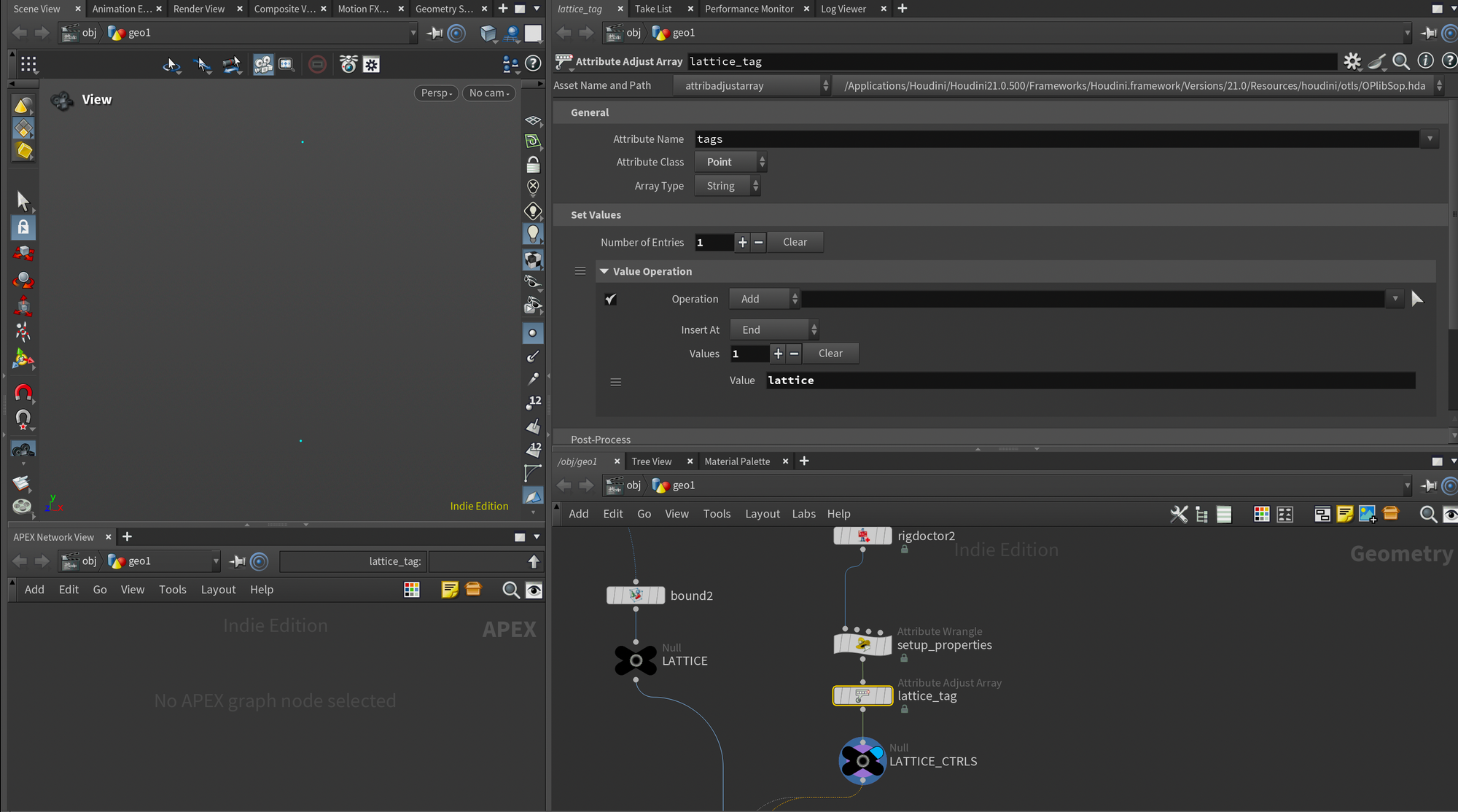
Finally I added an Attribute Adjust Array node to add a tag to our lattice controls. I briefly covered tags in my earlier APEX post, but essentially they are a simple bookmark for us to easily find any of our lattice controls when we start working in APEX.
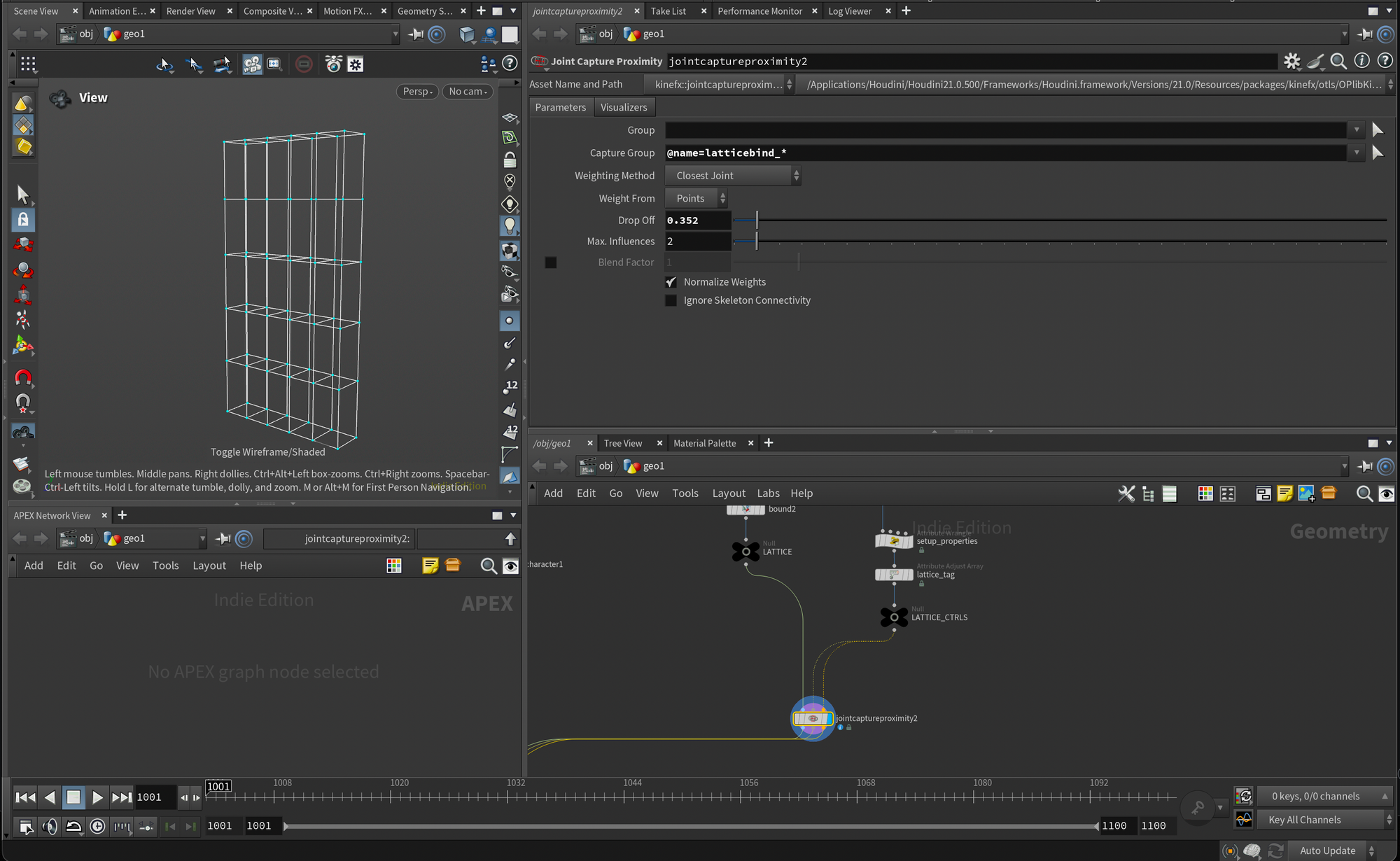
Finally I skinned the lattice controls to the lattice mesh so we can deform it using our joints. I did this with a Joint Capture Proximity node again but you can skin it however you prefer.
Step 3: Add Lattice to Character Folder
Next, we need to add our lattice to our character folder. This is needed so that we can pull the geometry and controls into our APEX rig.
Simplest way to do this is to add another APEX Pack Character by plugging in the output of our previous APEX Pack Character into the first input, and the outputs of our Joint Capture Proximity from the lattice section into the second, third, and fourth input.
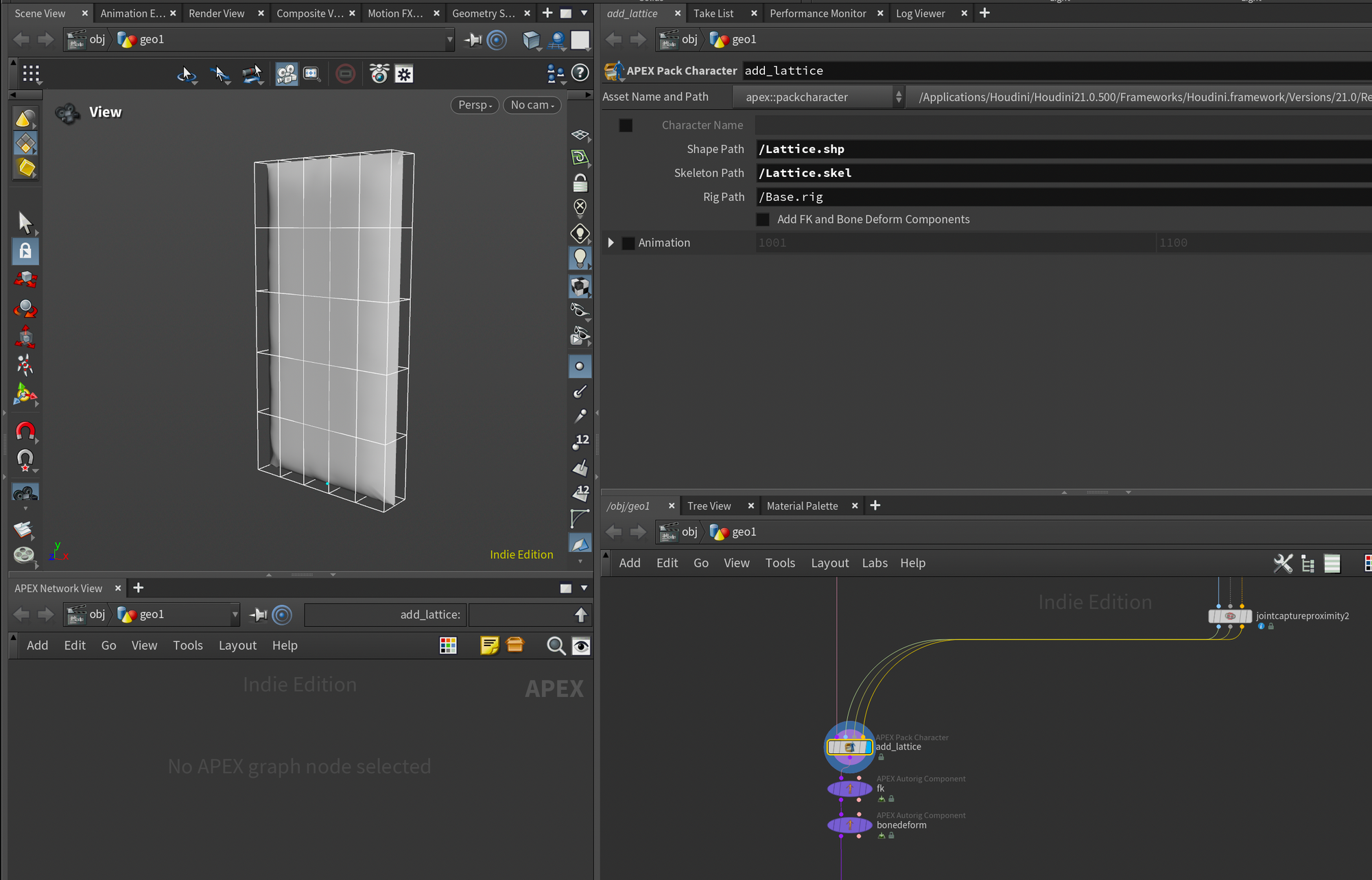
You'll also need to change the Shape Path and Skeleton Path in the APEX Pack Character to /Lattice.shp and /Lattice.skel like you see below, since we need to have these separate from the Base.shp and Base.skel.
From here I set up my standard bonedeform and fk using APEX Autorig Components.
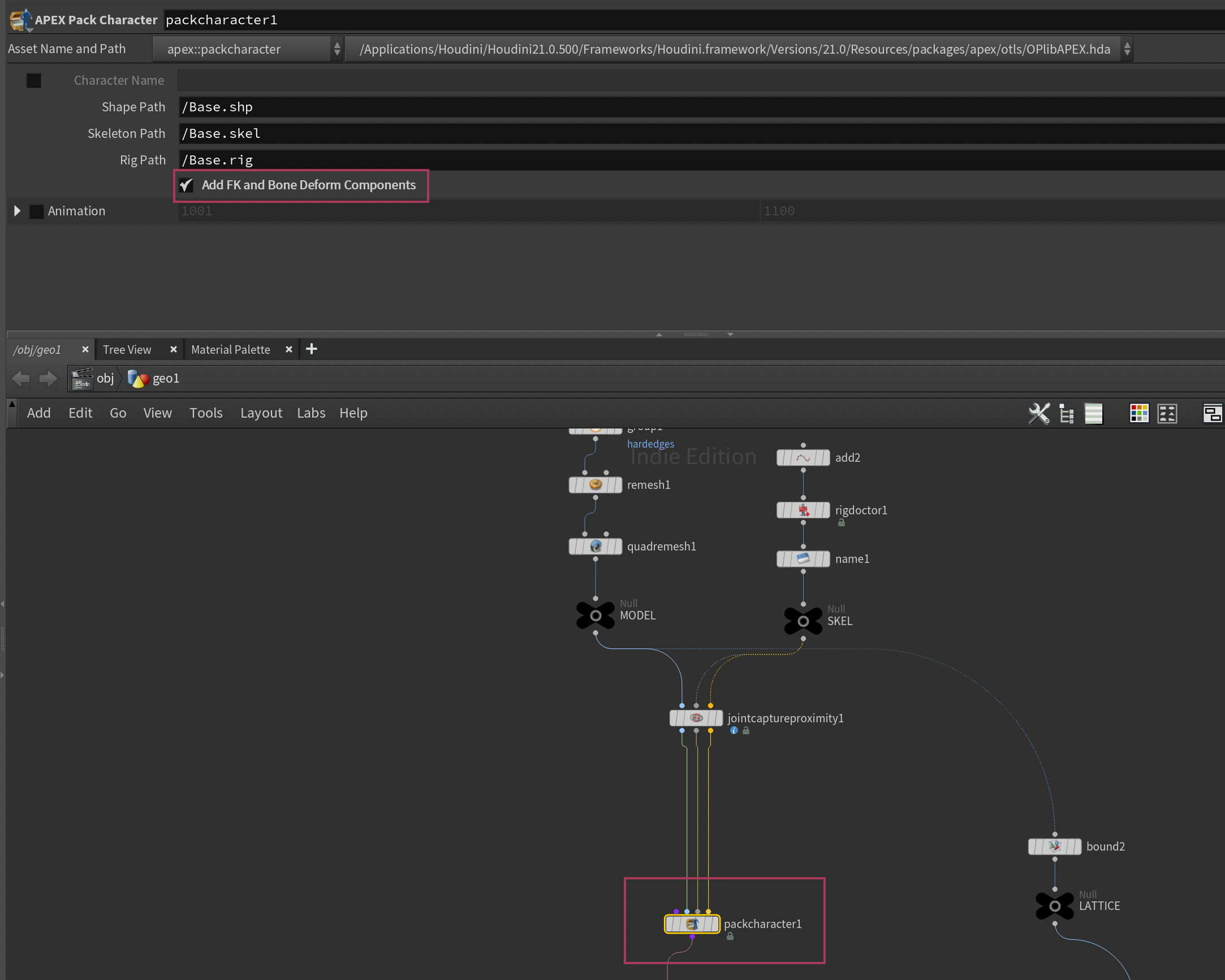
Since this is an action you perform so often when setting up APEX rigs, SideFX actually made an even faster way to do it now, directly in the APEX Pack Character node. If you go back to the first APEX Pack Character we made (the one with the root joint and pillow mesh) you can turn on Add FK and Bone Deform Components. This saves you the extra step of having to add them yourself after.
Step 4: Initialize Lattice Controls
Now we have to initialize our lattice controls. Meaning we essentially want to add them into our APEX Graph as TransformObjects.
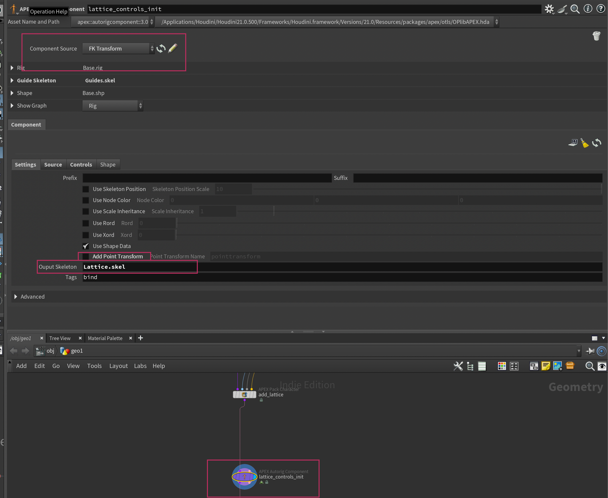
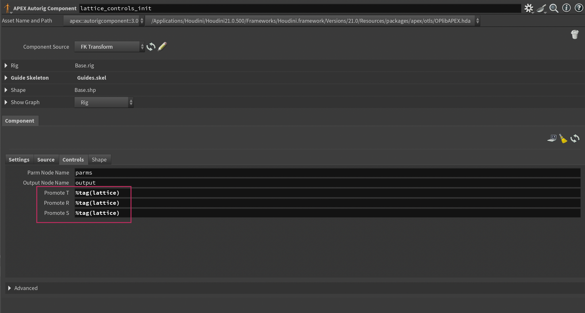
Drop down a new APEX Autorig Component and set the component source to FK Transform. Next, on the Settings tab, set the Output Skeleton to Lattice.skel (this is the name of the skeleton element containing the lattice controls). You'll also need to disable Add Point Transform as my script takes care of that part.
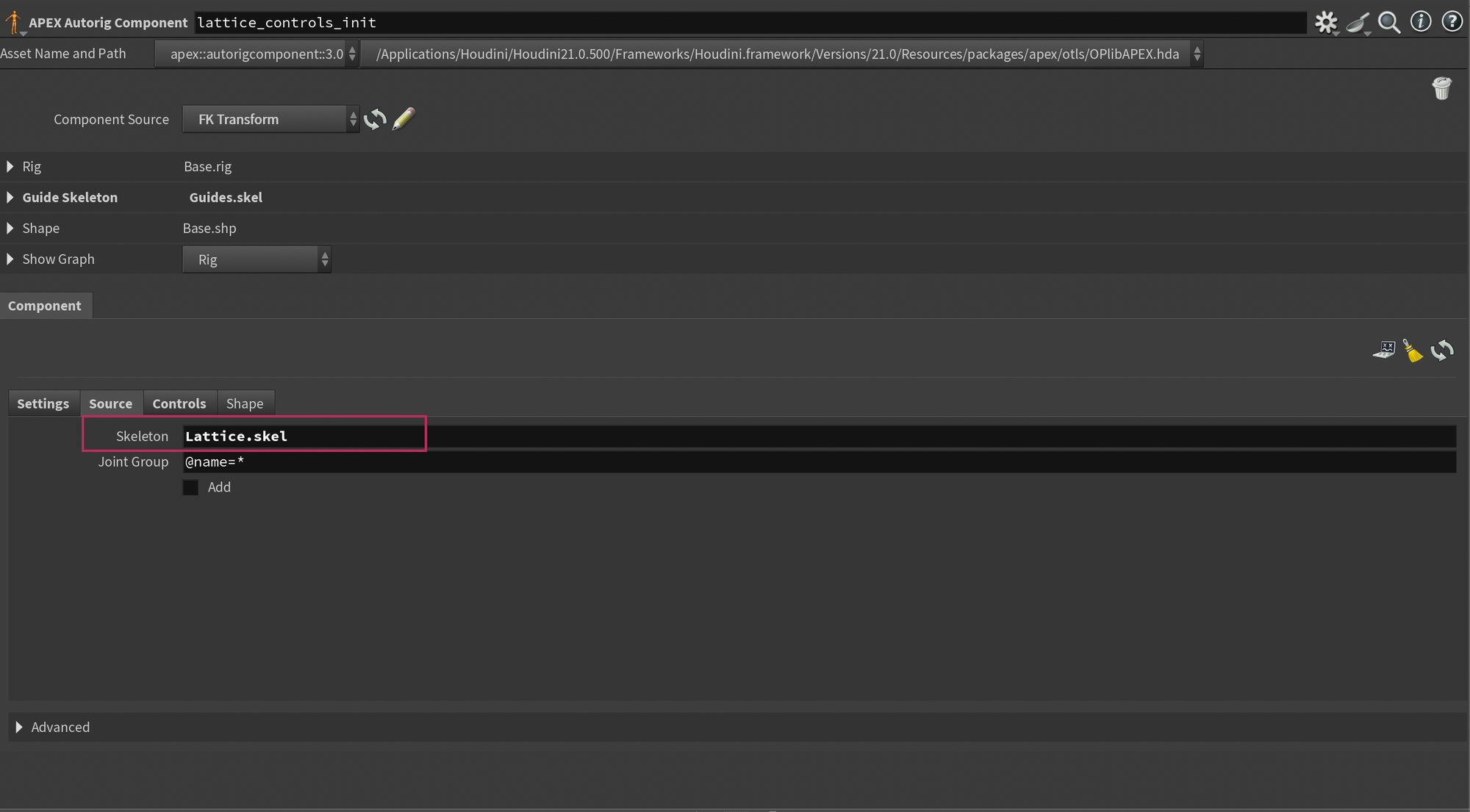
On the Source tab you'll also need to change the Skeleton to Lattice.skel so it pulls the skeleton data from that element.
And finally, in the Controls tab - change the Promote TRS to %tag(lattice).
Step 5: Configure Lattice
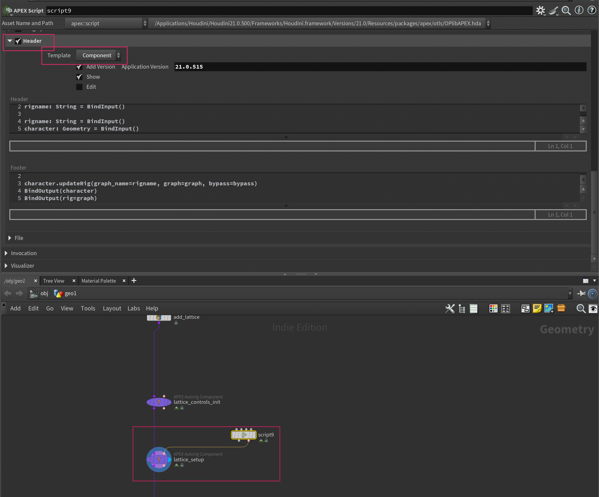
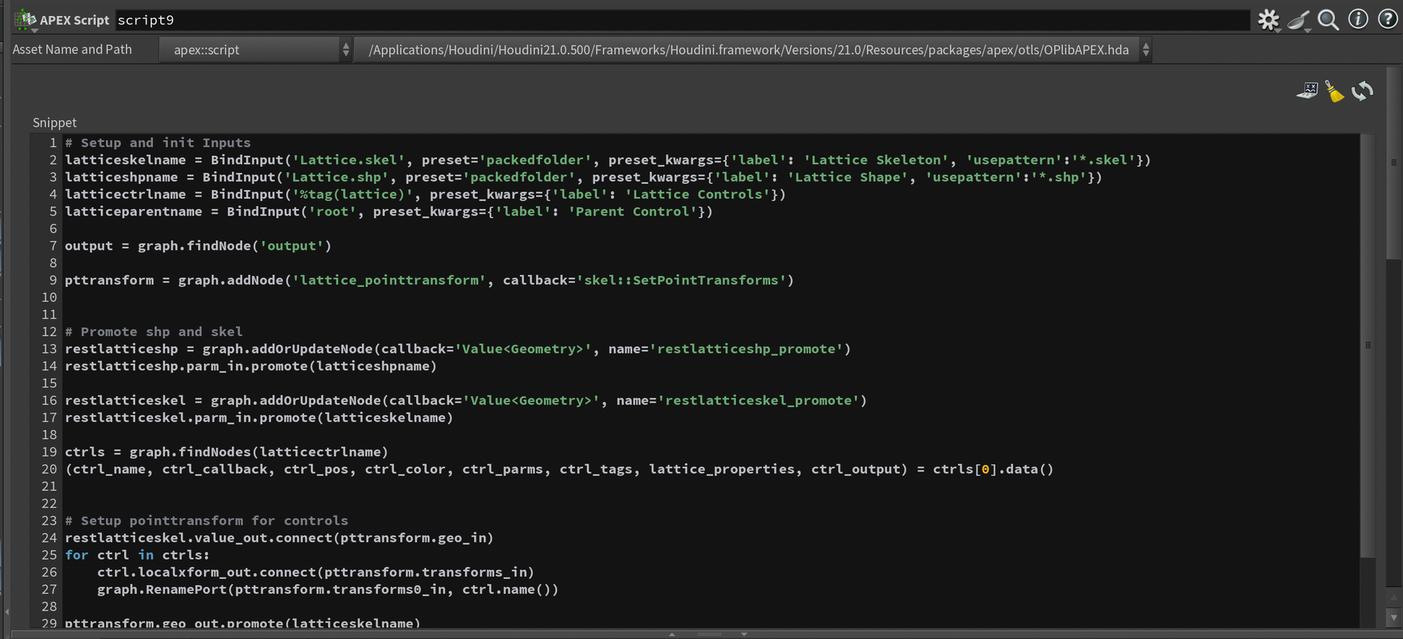
Now we only need to add the custom lattice rig component and we're done. Drop down another APEX Autorig Component and set the Component Source to Use Second Input. Then, drop down an APEX Script node and paste the following code into the Snippet section.
# Setup and init Inputs
latticeskelname = BindInput('Lattice.skel', preset='packedfolder', preset_kwargs={'label': 'Lattice Skeleton', 'usepattern':'*.skel'})
latticeshpname = BindInput('Lattice.shp', preset='packedfolder', preset_kwargs={'label': 'Lattice Shape', 'usepattern':'*.shp'})
latticectrlname = BindInput('%tag(lattice)', preset_kwargs={'label': 'Lattice Controls'})
latticeparentname = BindInput('root', preset_kwargs={'label': 'Parent Control'})
output = graph.findNode('output')
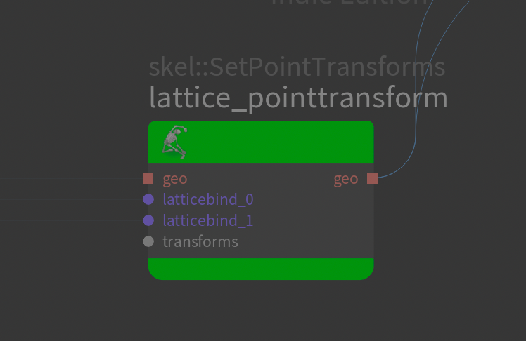
pttransform = graph.addNode('lattice_pointtransform', callback='skel::SetPointTransforms')
# Promote shp and skel
restlatticeshp = graph.addOrUpdateNode(callback='Value<Geometry>', name='restlatticeshp_promote')
restlatticeshp.parm_in.promote(latticeshpname)
restlatticeskel = graph.addOrUpdateNode(callback='Value<Geometry>', name='restlatticeskel_promote')
restlatticeskel.parm_in.promote(latticeskelname)
ctrls = graph.findNodes(latticectrlname)
lattice_properties = ctrls[0].properties()
# Setup pointtransform for controls
restlatticeskel.value_out.connect(pttransform.geo_in)
for ctrl in ctrls:
ctrl.localxform_out.connect(pttransform.transforms_in)
graph.RenamePort(pttransform.transforms0_in, ctrl.name())
pttransform.geo_out.promote(latticeskelname)
# Setup bonedeform
bonedeform = graph.addNode('lattice_bonedeform', callback='sop::bonedeform')
pttransform.geo_out.connect(bonedeform.geo2_in)
restlatticeskel.value_out.connect(bonedeform.geo1_in)
restlatticeshp.value_out.connect(bonedeform.geo0_in)
# Setup lattice
lattice = graph.addNode('lattice_deformer', callback='geo::Lattice::2.0')
divsx: Int = lattice_properties['divsx']
divsy: Int = lattice_properties['divsy']
divsz: Int = lattice_properties['divsz']
lattice.setParms({'divsx':divsx, 'divsy':divsy, 'divsz':divsz})
restlatticeshp.value_out.connect(lattice.restlattice_in)
baseshp_input_port: ApexPortID = output.port('Base.shp').connected()[0]
# Parent lattice controls if specified
parent_ctrl: ApexNodeID = graph.findNode(latticeparentname)
for ctrl in ctrls:
parent_ctrl.xform_out.connect(ctrl.parent_in)
parent_ctrl.localxform_out.connect(ctrl.parentlocal_in)
# Connect to bonedeformation
baseshp_node: ApexNodeID = baseshp_input_port.node()
baseshp_source_port: ApexPortID = baseshp_node.port('geo0[in]').connected()[0]
baseshp_source_port.connect(lattice.geo_in)
lattice.geo_out.connect(baseshp_node.geo0_in)
bonedeform.geo_out.connect(lattice.deformedlattice_in)Lattice Rig Component Script.
You'll also need to turn on the Header section of the APEX Script node, and set the Template to Component. This will initialize some attributes commonly used for rig components. The script won't work without this enabled.
Finally, plug the output of this into your APEX Autorig Component and you're good to go (unless you want to tweak some settings - see below)!
Step 7: Configure Lattice settings
If you've followed along and are using the same scene as me, everything should work with the defaults, and you should now have a working lattice deformer in your rig. You can press Enter in the viewport and try to move around the lattice controls to check.
However, if you're using this setup in your own rig, I've exposed some options that you may want to take a look at. Here's a breakdown. These parameters will show up in the APEX Autorig Component that you plugged the APEX Script into. Not the APEX Script node itself.
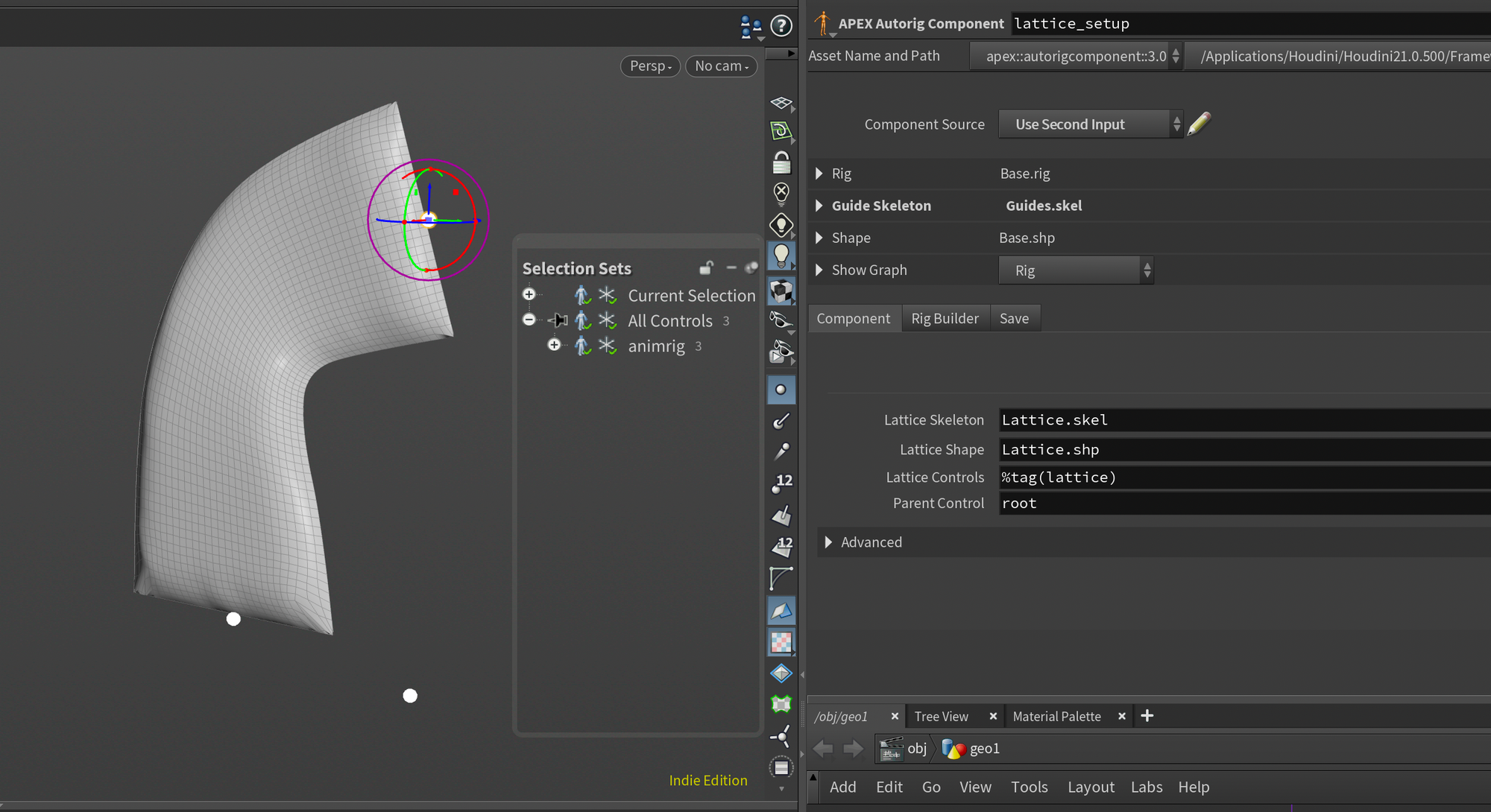
Lattice Skeleton - This is the name of the skeleton (.skel) element in your character folder that contains the lattice controls.
Lattice Shape - This is the name of the shape (.shp) element in your character folder that contains the lattice mesh.
Lattice Controls - This is the name of your lattice controls. You can use regular expressions or tags like I do.
Parent Control - This is the name of a single control/joint that you want to parent the lattice controls under. This makes sure that you can move the root control without breaking the lattice deformation.
After performing the setup above, you can continue with your rig, maybe add wrinkles using the APEX Add Wrinkles node, or configure controls to prepare a proper user interface for your animator.
Lattice Rig Script Breakdown
Breaking down script functionality.
In this section, I wanted to do a small breakdown of the APEX Script as there aren't too many resources on learning it yet. Again, I want to preface this by saying that I still have plenty to learn about APEX Script, so I'm all ears if someone has ideas for improvements.
I do hope this might help start your own journey with APEX Script.
Before we start the breakdown, I want to share how I approach building APEX Scripts, as I find that it can be a little bit daunting.
APEX Graph vs. APEX Script
The first question you have might be when you should use APEX Script and when you should create your Rig Component using the regular APEX Graph. Unfortunately, there is no clear answer to this question - it's quite similar to the difference between when to use VEX and VOPs.
It's also important to note that APEX is a little different since it has an additional layer of abstraction.
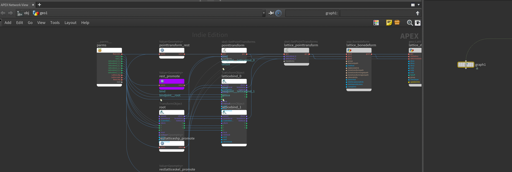
You have the main rig APEX graph, which is what you see when you edit the rig directly by appending an APEX Graph node after your APEX Autorig Component. This is actually what's stored in the Base.rig element of your Character Folder and will be what you save out with your character. If you were to edit this graph, you would see the impact directly, so this is a very useful way to prototype new functionality. This graph will likely also feel more natural to work with if you're used to other parts of Houdini.
APEX Autorig Component set to Fuse Graph. This provides a destructive way of working with your rig which can be useful for quick fixes.The other layer of abstraction I mentioned is the Rig Components. This is the procedural part of APEX and what you'll be using to create reusable functionality like my Lattice Rig Component I shared above.
There are two main ways to create Rig Components in APEX, and both involve applying it to your rig through the second input of the APEX Autorig Component: APEX Script, and APEX Graph. Both options will have you create a recipe/instructions for APEX on what it should change in your rig.
For example, with the Lattice Rig Component above, it will take the settings provided and add, wire, and configure the nodes necessary to add a lattice deformer to your Rig. If we had done this manually by editing the rig graph instead of through a rig component, we wouldn't have been able to reuse it in other rigs.
With APEX Graph you'll define these instructions through nodes, by pulling in your existing rig and using nodes like FindNode, FindPort, ConnectInput, and AddNode to procedurally add new functionality to your rig.
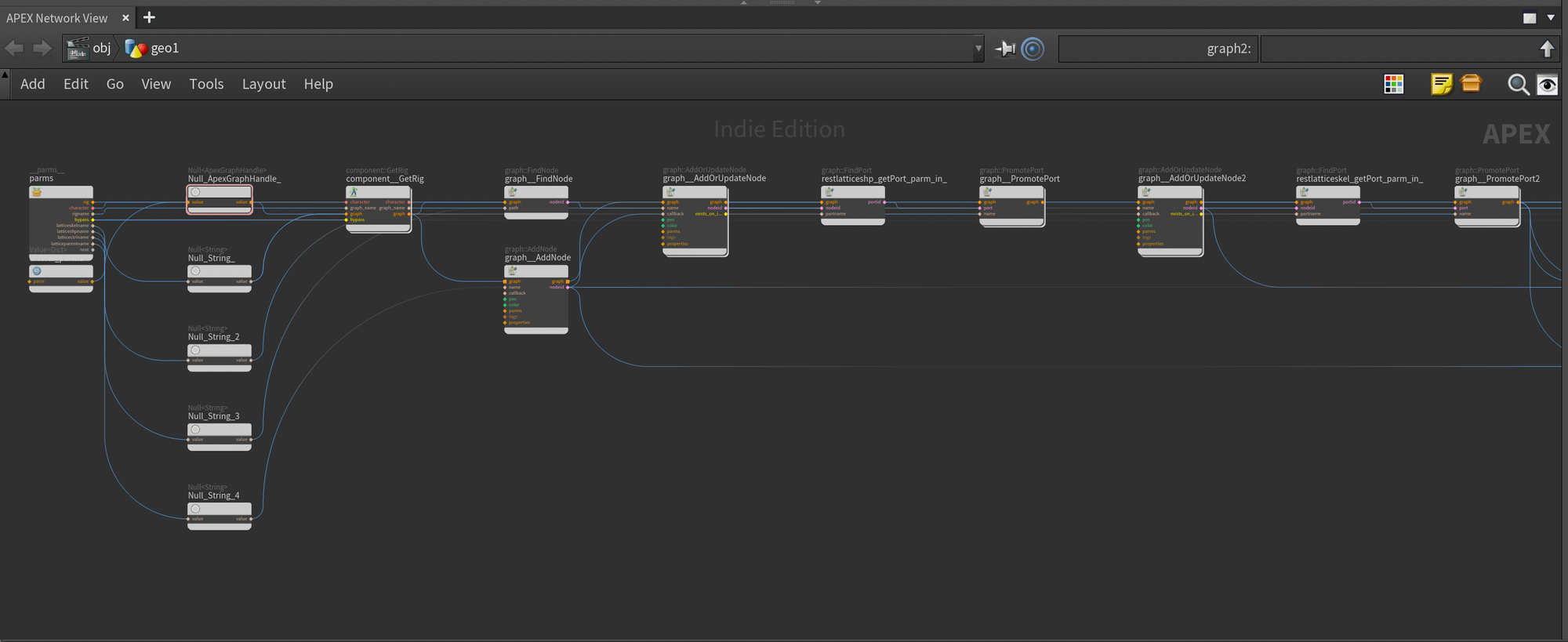
With APEX Script, it's the exact same idea, except you're doing it via a script instead of nodes. Personally, I find this approach a lot easier to manage because the amount of nodes required when setting up Rig Components using the APEX Graph can be quite large. Mainly because you need to be very explicit with everything. It's not uncommon for a couple of lines of APEX Script to correspond to many nodes in an APEX Graph.
The great thing is also that the APEX Script is still generating an APEX Graph Rig Component under the hood, so you're also able to modify the output of the script by editing the graph itself if you want.
Approaching Custom Rig Components
Before jumping into the breakdown, I wanted to share how I usually approach building Rig Components. I have it broken down into a small system, and although this might change in the future, I've found it to be quite efficient for writing Rig Components fast.
- Identify feature (what Rig Component do I need, how can I make it as generic as possible so I can reuse it for other rigs?)
- Prototype Feature by directly editing the rig graph with an
APEX Graph. This allows me to quickly figure out what nodes are needed and how I should connect everything. - Create APEX Script or APEX Graph Rig Component based on the component, with a focus on keeping the result as generic as possible so it can be reused. No hardcoding if it can be avoided.
I hope this section helps a bit with setting up your own rig components. Now, let's jump into the breakdown!
Breakdown of Lattice Rig Component
Setup and initialize inputs
I will go section by section here and describe how each section of the script works.
# Setup and init Inputs
latticeskelname = BindInput('Lattice.skel', preset='packedfolder', preset_kwargs={'label': 'Lattice Skeleton', 'usepattern':'*.skel'})
latticeshpname = BindInput('Lattice.shp', preset='packedfolder', preset_kwargs={'label': 'Lattice Shape', 'usepattern':'*.shp'})
latticectrlname = BindInput('%tag(lattice)', preset_kwargs={'label': 'Lattice Controls'})
latticeparentname = BindInput('root', preset_kwargs={'label': 'Parent Control'})

output = graph.findNode('output')

pttransform = graph.addNode('lattice_pointtransform', callback='skel::SetPointTransforms')
Here we first define a bunch of variables with BindInput. These are the settings that show up on the Autorig Component node. The preset_kwargs are used to define the label, preset, and default value.
Following that, we look for the output node of the APEX Rig as we need to pull an input from that later (I'm fairly certain there's a better way to do this, but this works).
Finally we create a SetPointTransforms node. This node is used to update the placement of joints/controls. I added this manually because we didn't do it in the FK Transform Rig Component earlier for the lattice controls. We add it here because we want to customize what we input into this later.
Promote Lattice.shp and Lattice.skel
# Promote shp and skel
restlatticeshp = graph.addOrUpdateNode(callback='Value<Geometry>', name='restlatticeshp_promote')
restlatticeshp.parm_in.promote(latticeshpname)

restlatticeskel = graph.addOrUpdateNode(callback='Value<Geometry>', name='restlatticeskel_promote')
restlatticeskel.parm_in.promote(latticeskelname)

ctrls = graph.findNodes(latticectrlname)
lattice_properties = ctrls[0].properties()
Here we promote our Lattice.shp and Lattice.skel using the attributes established in the previous section. This allows us to store a pointer to those inputs as a variable.
We also add a new variable called ctrls that contains all of our Lattice Controls. We then use the special properties() function to pull in the properties dictionary (lattice_properties) from the control (which in our case will be used to get the divx/y/z of the lattice since we store that on the control properties).
We're only requesting data from the first control (index 0) since we're just looking for the divx/y/z and that particular property is the same on all controls.
Setup pointtransform for Controls
# Setup pointtransform for controls
restlatticeskel.value_out.connect(pttransform.geo_in)
for ctrl in ctrls:
    ctrl.localxform_out.connect(pttransform.transforms_in)
    graph.RenamePort(pttransform.transforms0_in, ctrl.name())

pttransform.geo_out.promote(latticeskelname)
Here we set up the SetPointTransforms node which updates the control positions in our Lattice.skel. This is done by connecting the base Lattice.skel and iterating over each control, connecting it to the SetPointTransforms node and renaming the inputs to be the name of the control. It's important that the inputs have the correct names.
Finally we promote the output of the SetPointTransforms which is what enables the changes recorded by the SetPointTransforms to update the actual rig output (this is the equivalent of plugging a node into the output node of an APEX Graph.
Setup Lattice Bonedeform
# Setup bonedeform
bonedeform = graph.addNode('lattice_bonedeform', callback='sop::bonedeform')

pttransform.geo_out.connect(bonedeform.geo2_in)
restlatticeskel.value_out.connect(bonedeform.geo1_in)
restlatticeshp.value_out.connect(bonedeform.geo0_in)
Next we setup a custom bonedeform node for our Lattice. This is what will deform our lattice mesh using the lattice controls. We connect the Lattice.shp to the first input, the Lattice.skel to the second input (rest Lattice.skel), and the deformed Lattice.skel (the output from our SetPointTransforms) to the third input.
Setup Lattice
# Setup lattice
lattice = graph.addNode('lattice_deformer', callback='geo::Lattice::2.0')

divsx: Int = lattice_properties['divsx']
divsy: Int = lattice_properties['divsy']
divsz: Int = lattice_properties['divsz']
lattice.setParms({'divsx':divsx, 'divsy':divsy, 'divsz':divsz})
restlatticeshp.value_out.connect(lattice.restlattice_in)
baseshp_input_port: ApexPortID = output.port('Base.shp').connected()[0]
Next we'll setup the Lattice node itself. We do that by adding a new node using the callback geo::Lattice::2.0 (callback is basically the type of the node we're adding).
We then update the Lattice parameters by pulling in the divx/y/z and connecting the rest Lattice.shp into the restlattice_in input.
We also establish a new variable called baseshp_input_port which stores the output port containing Base.shp (we'll need to replace this wire later).
Setup Parent to Lattice Controls
# Parent lattice controls if specified
parent_ctrl: ApexNodeID = graph.findNode(latticeparentname)
for ctrl in ctrls:
    parent_ctrl.xform_out.connect(ctrl.parent_in)
    parent_ctrl.localxform_out.connect(ctrl.parentlocal_in)
Next we parent our lattice controls by finding the parent control using findNode and our latticeparentname variable (which stores the parent control we specified on the Autorig Component - in our case root).
We then iterate over each control and connect the the xform and localxform to the parent and parentlocal of each lattice control.
Finishing Up
# Connect to bonedeformation
baseshp_node: ApexNodeID = baseshp_input_port.node()
baseshp_source_port: ApexPortID = baseshp_node.port('geo0[in]').connected()[0]
baseshp_source_port.connect(lattice.geo_in)
lattice.geo_out.connect(baseshp_node.geo0_in)
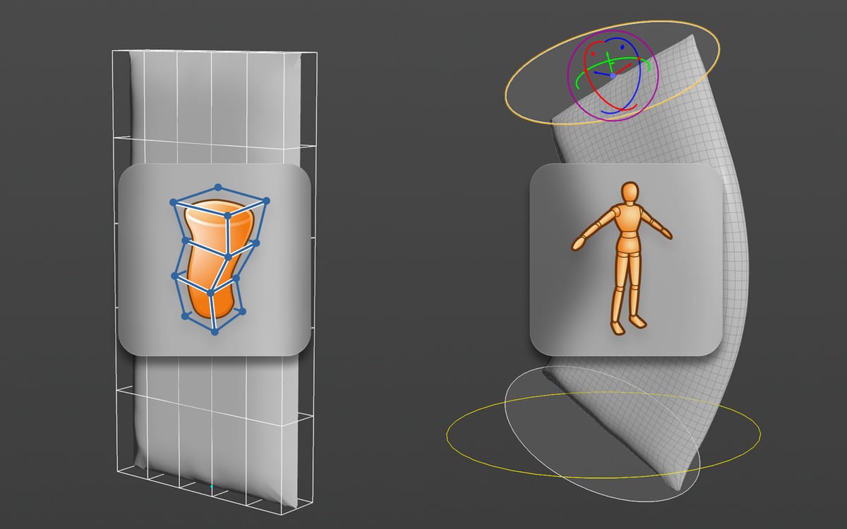
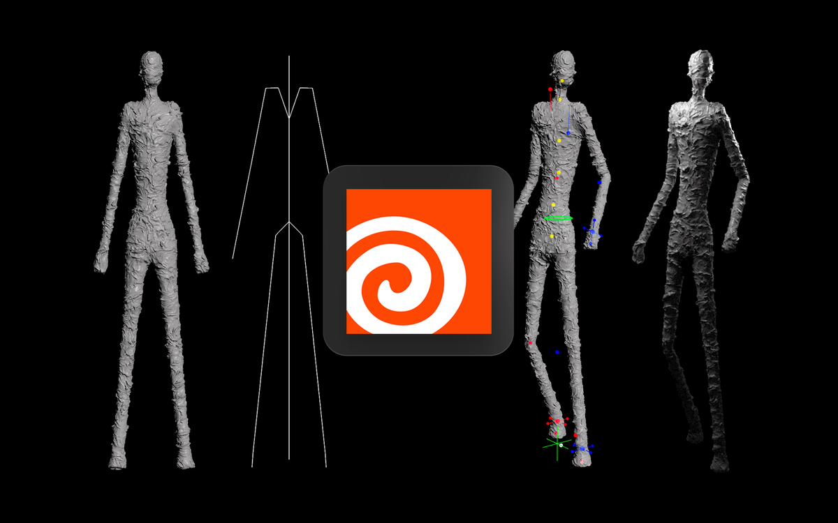
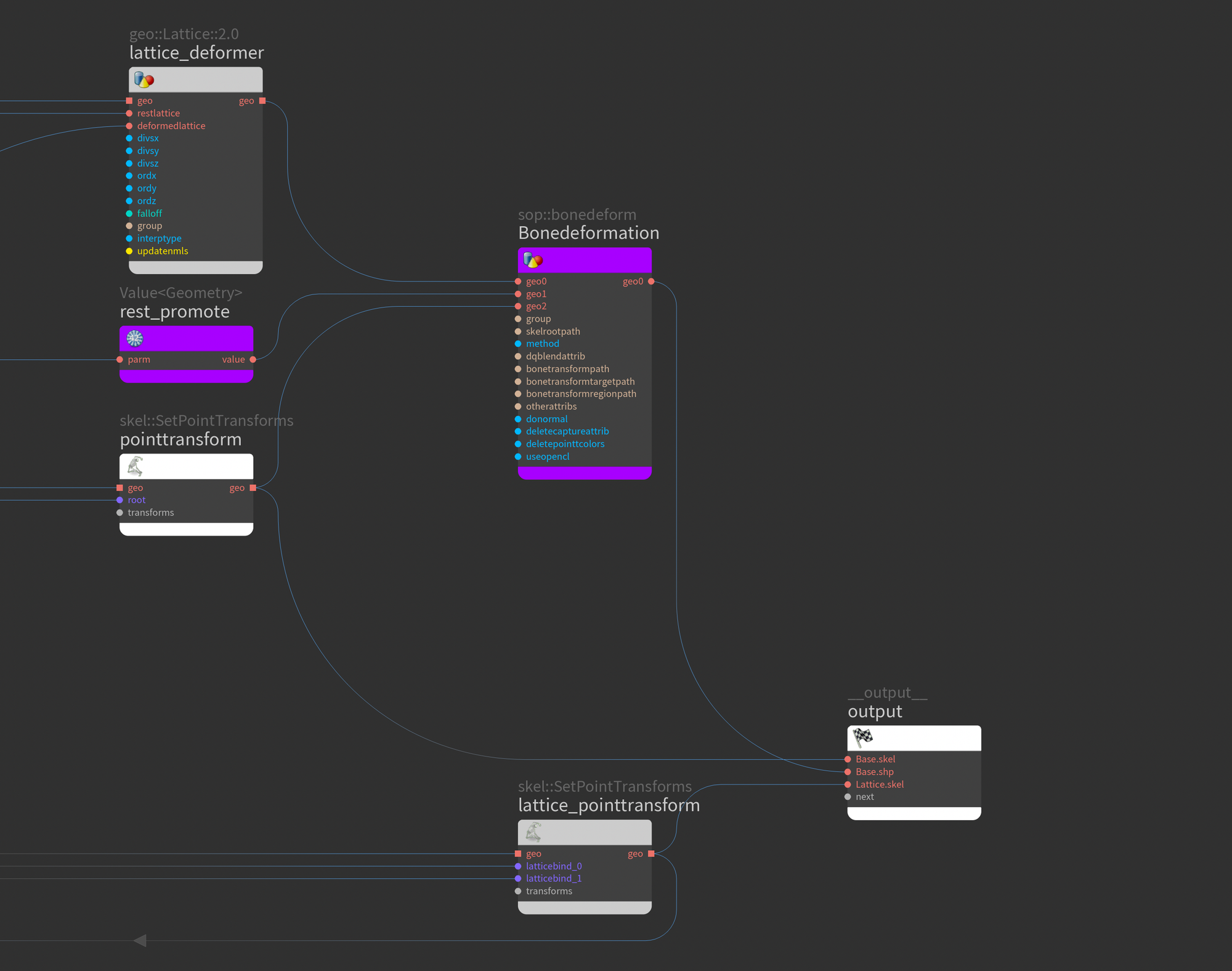
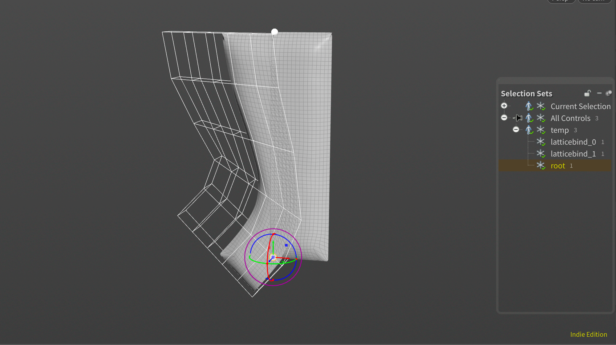
bonedeform.geo_out.connect(lattice.deformedlattice_in)Finally, we wrap up and connect the last remaining bits. This part is crucial as the order of operations is quite important. We have to do the bind joint Bonedeform at the very end. If we do the Lattice deform last on the already deformed output, we'll get results like we see in the second screenshot below.
Conclusion
Thanks for reading!
And that should wrap up the Lattice Deform Rig Component! There's a lot to explore around APEX, and I hope to dive into it even more this year. Happy new year to everyone reading, and thank you for checking out this post! If you have any questions, feel free to ask them below.
Also, if you'd like to get all of my posts directly to your inbox, feel free to subscribe to my newsletter below.
Finally, if you're interested in the project files for this post, you can grab it for free on Gumroad below: