Basic Auto-rigging in APEX with Houdini 20
One of the most exciting additions in Houdini 20 is the APEX system. In its current state, it is primarily useful for rigging, but in the future, SideFX hints that it might be used in other areas as well.
There isn't too much documentation about the core functionality of APEX as I'm writing this, but in essence, it's described as a very optimized graph network that sits as a layer below SOPs and can be accessed through Python, SOPs, or even context-specific nodes.
SideFX is primarily pushing APEX with an entirely new animation workflow that consists of building your skeleton in SOPs (the same way as you would have done with KineFX) and then building a procedural APEX rig on top using various rig components. In this article, I will cover how to set up a basic rig using these new tools, while keeping it as procedural as I can so you can reuse parts of the graph.
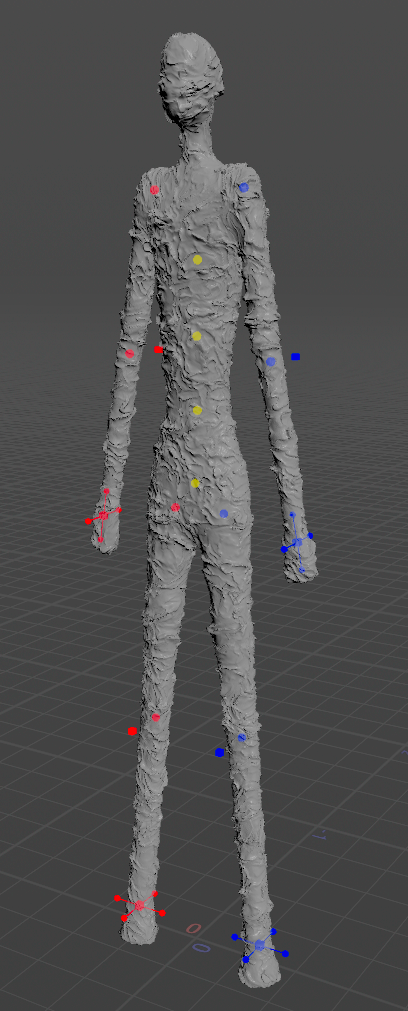
For this project, I'll be rigging this simple Giacometti-like sculpture guy I created. Since I want to keep this basic (and since my model has no hands or feet) I won't cover how to rig things like reverse foot and FK fingers. However, SideFX has a good example hip-file you can explore here to see how that's done: https://www.sidefx.com/contentlibrary/electra-rig/
Preparing for APEX
Joint placement, skinning, and packing.
Skeleton
To start we need a skeleton for our character. You could in theory create this using any combination of SOP nodes, but the easiest way is using the Skeleton SOP. It's pretty intuitive, but I'll share a few useful tips below:
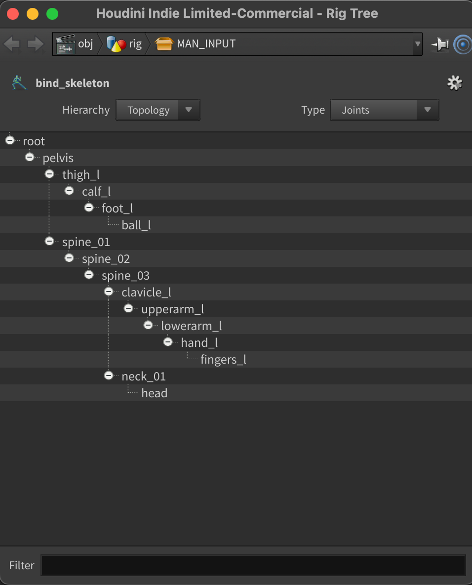
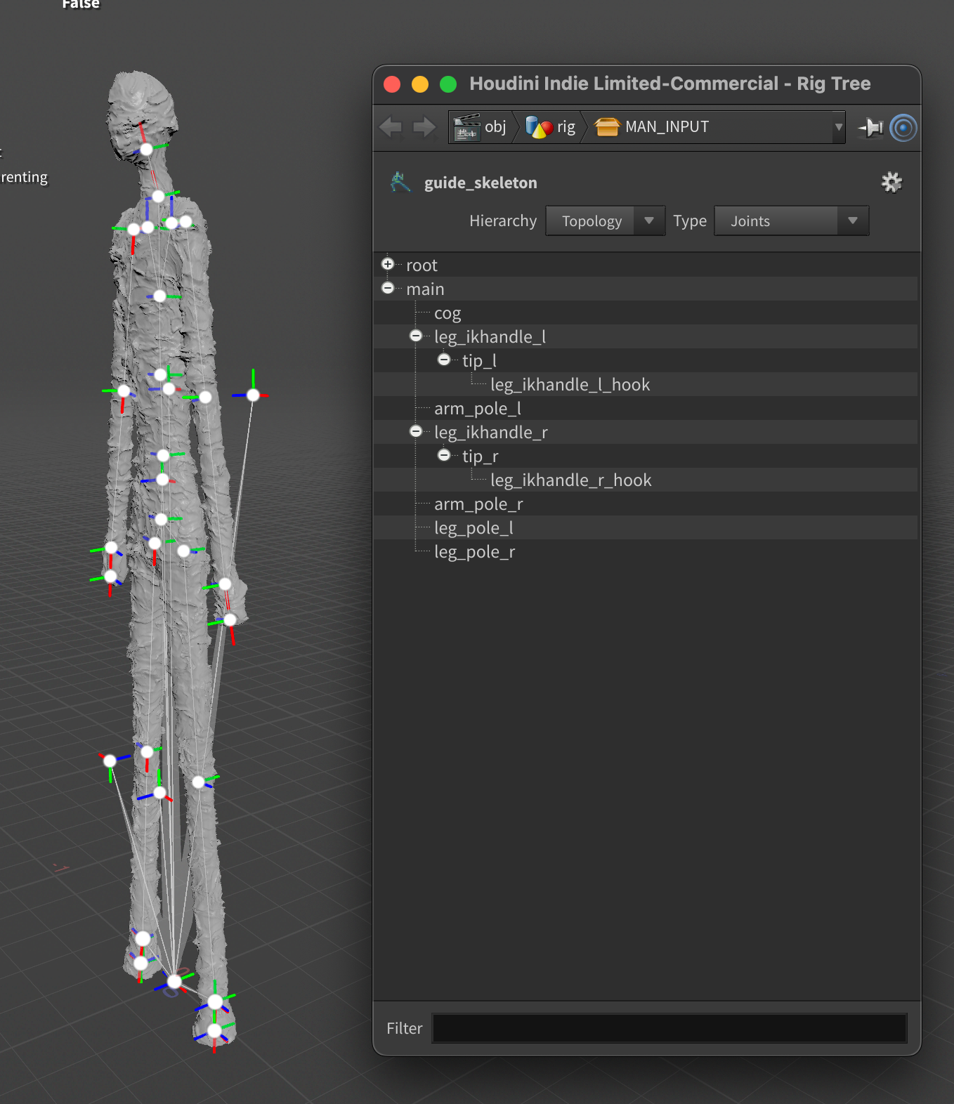
Rig Tree
When working inside the skeleton SOP it can be useful to view the hierarchy of joints (similar to looking in the outliner in Maya). You can access this by right-clicking your skeleton SOP node and clicking "Rig Tree".
Here you can re-organize the skeleton by dragging, or rename by double-clicking.
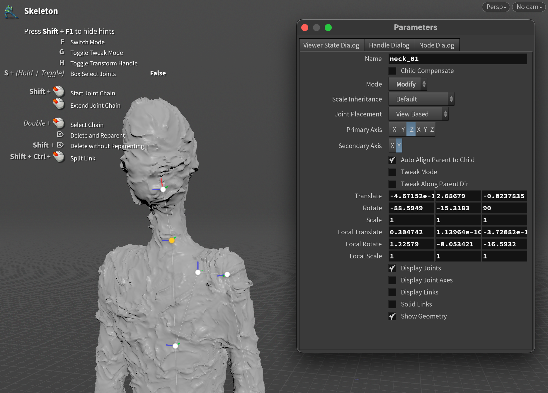
Fine-tuning individual joints
If you want to adjust the exact transforms of individual joints, you can press P while you have a joint selected and have your mouse hovering over the viewport. This will give you a new window with lots of parameters for tweaking positions and orientations to your liking.
Joint Orientations
Good joint orientations are essential for good rigs. If you're new to rigging there's a great explainer here: https://www.riggingdojo.com/2014/10/03/everything-thought-knew-maya-joint-orient-wrong/
The article above is technically about Maya, but the same fundamentals apply.
To set joint orientations in Houdini you can either rotate the joints yourself using the Skeleton SOP (ideally with child compensate and tweak mode on) or set a Primary and Secondary Axis using the Parameters window I showed above. After setting that you can simply select and right-click on your joint-chain and choose Orient Selected Joints.
You can check your joint orientations either by looking in the viewport when using the Skeleton SOP, or using a Rig Visualize SOP.
Skinning
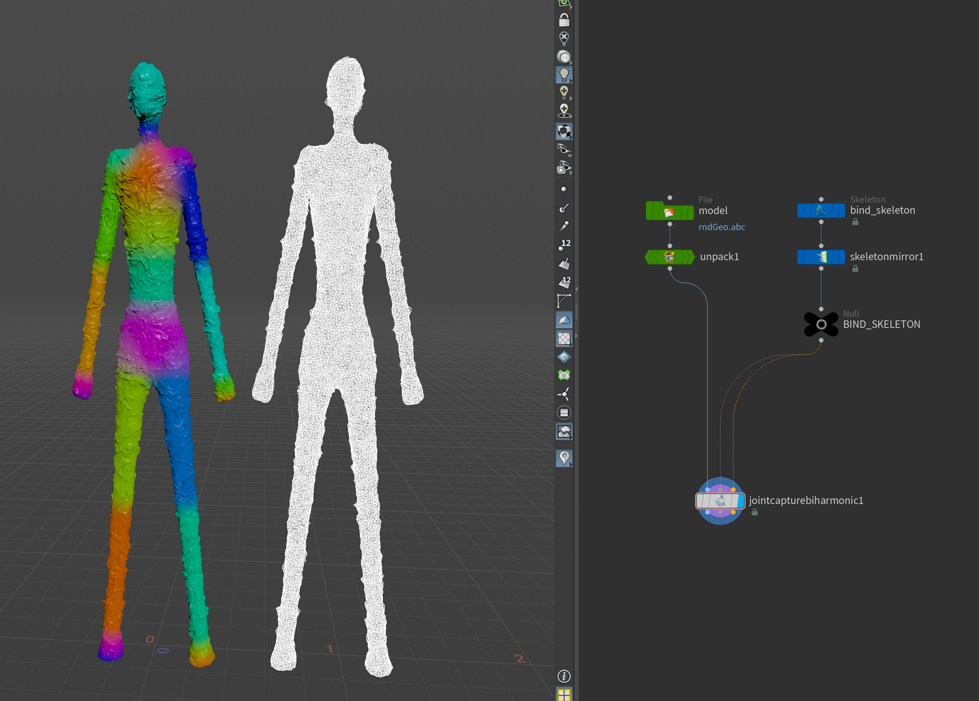
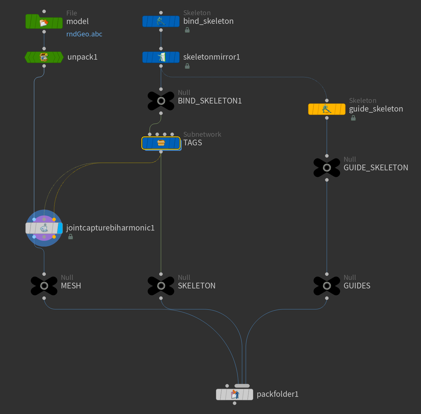
Houdini has a very procedural approach to skinning. Most of the time you can get 80% of the way simply by adding a Joint Capture Biharmonic SOP. This node takes in 3 inputs - rest geo, capture pose, and animated pose.
When preparing a rig for rigging in APEX you simply plug your skeleton into both the capture pose and animated pose inputs and voilà - you have a skinned mesh.
Now, while the Join Capture Biharmonic node gives you a very good starting point it is often necessary to modify some of your weights. This can luckily also be done in a very procedural manner using the Capture Layer Paint SOP. Simply add this after you Join Capture Biharmonic node and start painting away!
And since it's Houdini and all the skinning is stored using point attributes you could even create custom adjustment tools. The sky is the limit!
Tags
Now we start moving into more APEX (or rather Rig Component)-specific additions.
When using the new Rig Component nodes for auto-rigging it is very useful to add different tags to your joints so the Rig Component graph you create can easily be re-used for multiple characters as long as they have the same tags.
As of writing this, there is no proper UI for adding these tags, so we must resort to VEX. Luckily it is super easy to configure.
All you have to do is append your desired tag(s) to your joints in a special point attribute string called "tags". You must use append() rather than just setting the value directly as you likely want some joints to have multiple tags. Notice that the wrangle in the example targets joints based on their name attribute.
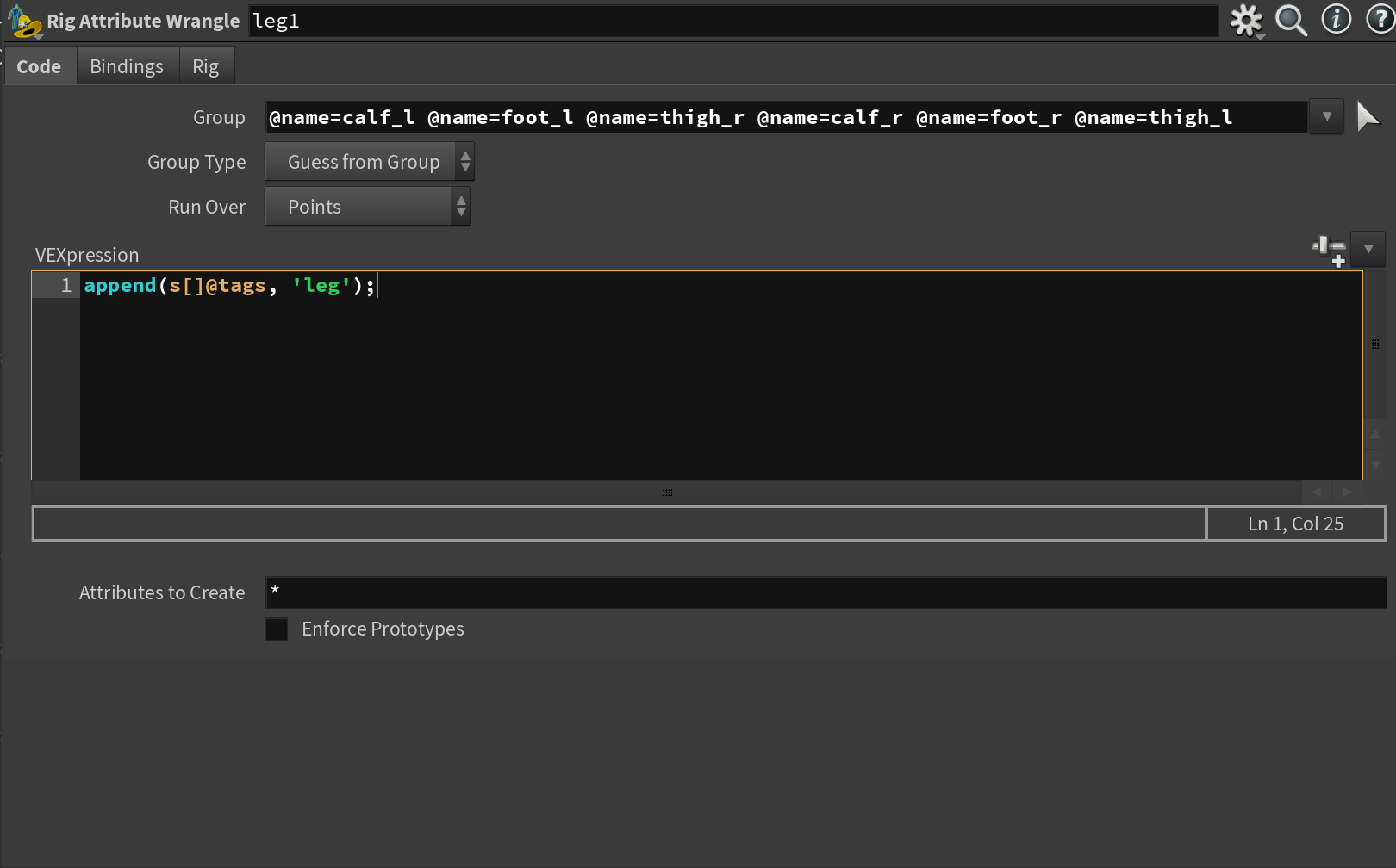
So how should you tag your joints? It very much depends on the rig but I recommend adding tags for legs, arms, right, left, ik, and fk, mid, and end (mid and end is for arms and legs so you know how the ik chain should be computed). This should give you a good starting point for when we start rigging. Always check your tags if something isn't working as expected - you can use the geometry spreadsheet to investigate individual joints.
Guide Skeleton
Lastly, it is often useful to create a guide skeleton. This is an extra skeleton hierarchy that contains your bind skeleton + any extra control joints you might need such as ik handles, pole vectors, etc.
For my rig I have mostly mimicked what SideFX created for their own Electra Rig (https://www.sidefx.com/contentlibrary/electra-rig/) as I found it to be a pretty good starting point. It doesn't contain any tags and is in essence just so we have the placements ready for all our additional controls. Notice that almost every joint is parented under one "main" joint placed at the origin.
Packing
When you've prepped the above it is time to move on to packing your character. This is a new system used by APEX and allows you to pack your character mesh, skeleton, and rig into one neat package. Think of it as if you're creating a folder structure for your rig like this:
/MyCharacter
  /Base.rig
  /Base.shp
  /Base.skel
  /Guides.skel
Creating this packed version of your character is the first step of creating a rig using APEX.
To do this you add a Pack Folder SOP and connect your skinned mesh, your skeleton, and your guide skeleton to the second input of the Pack Folder SOP.
Then, you need to define the name and type of your inputs in the Pack Folder SOP so it knows what the inputs are. Borrowing from SideFX's examples I tend to call my mesh "Base.shp", my skeleton "Base.skel", and my guides "Guides.skel". The most important part here is that you specify the right type for your input. You can see the available options by clicking on the index button to the right of the Type field.
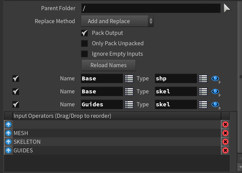
What about the rig though? Shouldn't there be a "Base.rig" too you might ask? That will be added automatically with Rig Component nodes. The "files" you see above are the only "files" we need to set up manually.
And now, we're ready to start doing some actual rigging!
Autorig Components
Configure FK
We'll start our rig by configuring a simple FK rig using the Rig Component node.
The Autorig Component node is the primary node you'll be using for creating rigs with APEX. In essence, it's a collection of presets for generating different parts of a rig. There are a lot of useful ones already built in, but you can extend this further and build custom rig components.
Under the hood the Autorig Component nodes setup an APEX Network. The primary advantage of rig components is that you won't need to interface with the actual APEX Network. So it saves you a level of complexity.
I would like to cover how to build custom rig components using the APEX graph in the future, but for this article, I'll stick to the built-in presets.
Now, back to setting up our FK rig. Start by creating an APEX Autorig Component and initialize the fktransform by selecting it from the Component dropdown.
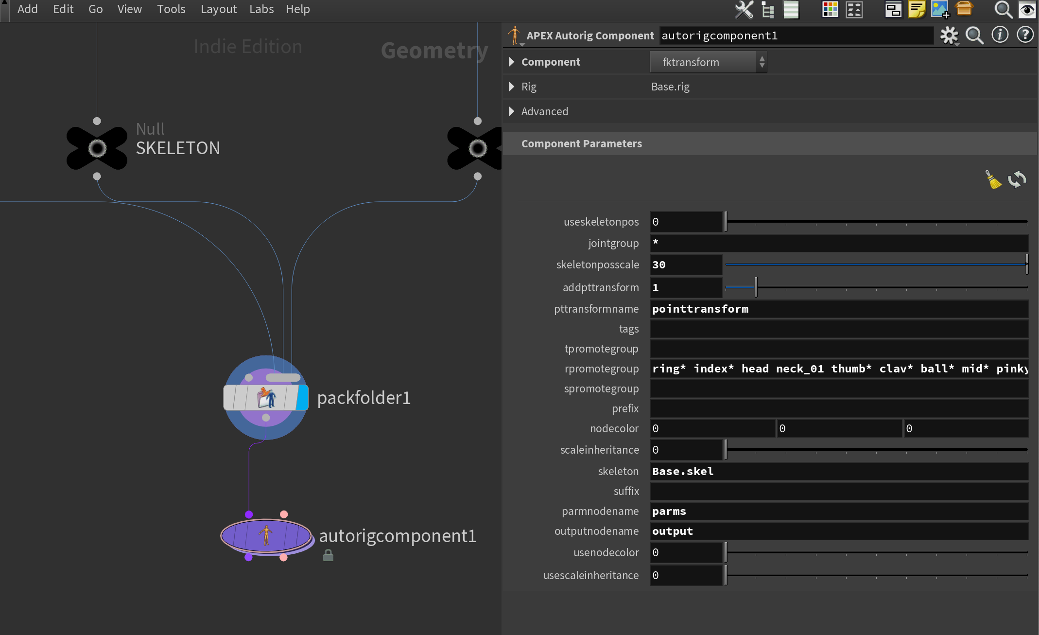
The parameters for this preset are a little daunting and the documentation is a bit lacking in this regard right now, but here are the essential parameters you should worry about:
- jointgroup = If you only want to work on a specific group of joints (remember you still need to add them in the rpromotegroup parameter).
- pttransformname = Name of the setpointtransforms node inside the APEX Network. This is the APEX Network node responsible for transforming your points in the end.
- t/r/spromotegroup = These are the lists of the joints you want to translate/rotate/scale in your FK rig setup. For FK you usually only want to add joints to the rpromotegroup parameter since you primarily want to target rotation. You can also use tags in this field. More on this later.
- skeleton = Name of the skeleton you want to activate the rig component on. Remember you need to be using the name you configured in the Pack Folder SOP.
- parmnodename = Name of the input parameter node in the APEX Network, this is the name of the node that feeds inputs from the outside into your APEX Network.
- outpostnodename = Name of the output parameter node in the APEX Network. This node is responsible for outputting information from the APEX Graph.
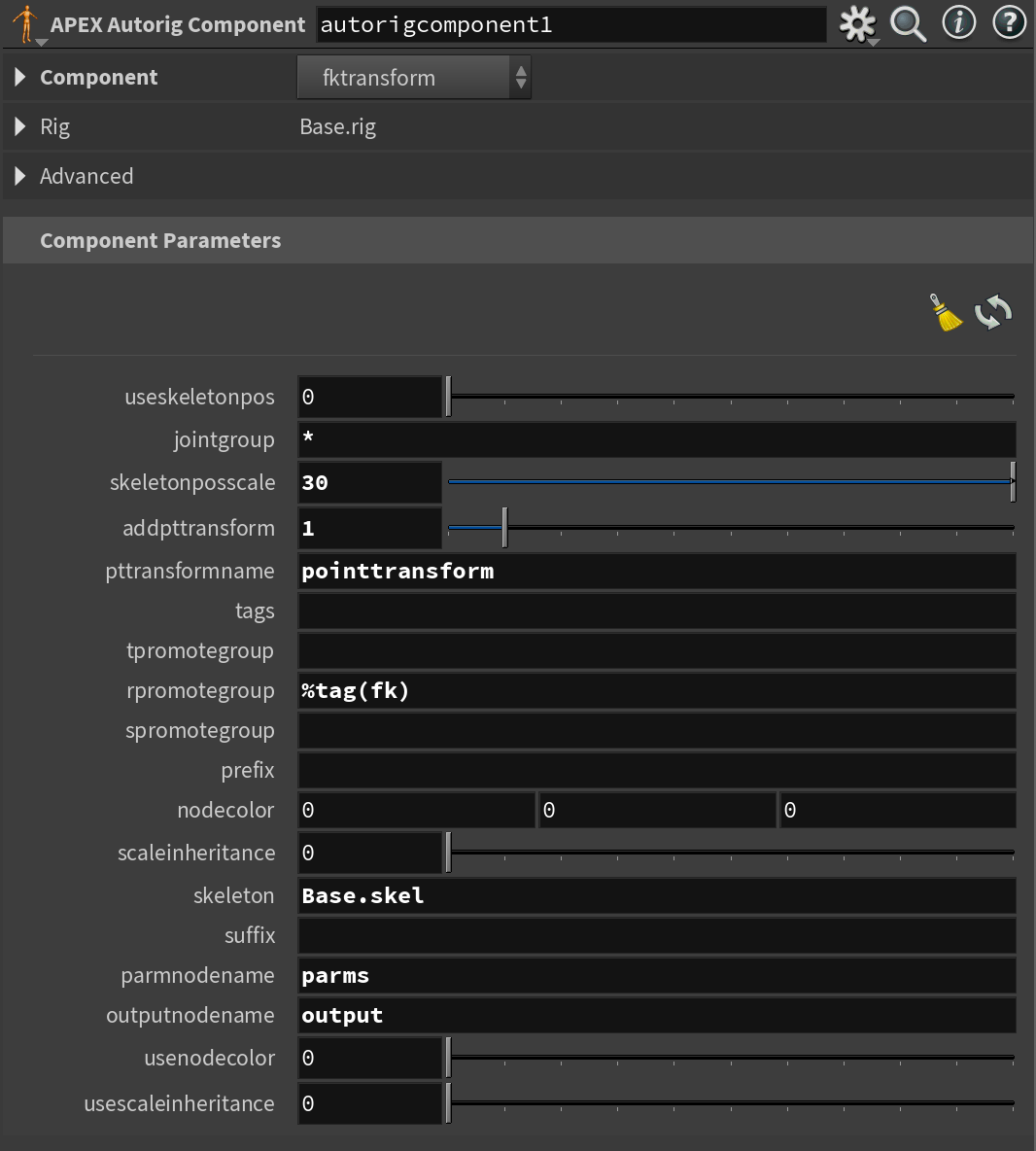
This node starts with a lot of good defaults so we don't need to adjust much. The primary thing you want to change is the name of the joints in the rpromotegroup. This can be done by either manually specifying which joints you want or using the tags we set up.
I'll be using tags, specifically I'll be targeting the joints I tagged with "fk" in the previous section. The syntax is shown below. Don't worry if you don't understand this, I'll expand on it shortly.
APEX Networks
Let's quickly step away from the actual rig and talk a bit about how APEX Networks are viewed.
As I mentioned earlier APEX Networks sit as a layer below SOPs and function as a separate network of nodes.
To access this APEX Graph we have to use a special new view inside Houdini called the "APEX Network View". Initially, when you open this new view it'll be empty. This is because we need to unpack our rig logic from the character folder.
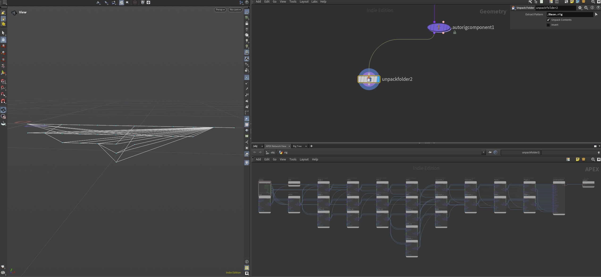
To do this, add an Unpack Folder SOP and append it to the first output (Character Stream) of your Rig Component. Then type in the path to the rig part of your character (in my case /Base.rig). If you're unsure about this path you can press the little arrow next to the field - it'll open up the Rig Tree so you can browse your character folder.
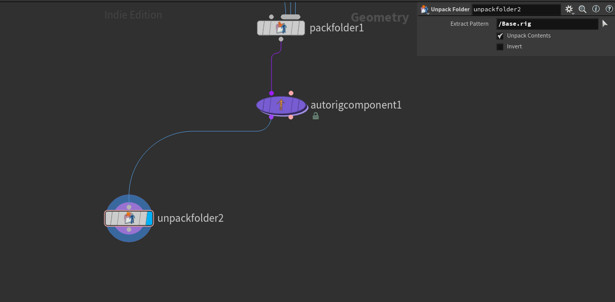
Now when you look in your APEX Network View you'll see it populated with nodes describing your current rig setup. You'll also get a representation of the network in the viewport since each node in APEX is represented by a point (this allows for some really interesting workflows).
For example, look at what happens to the network when you add a random color to each point.
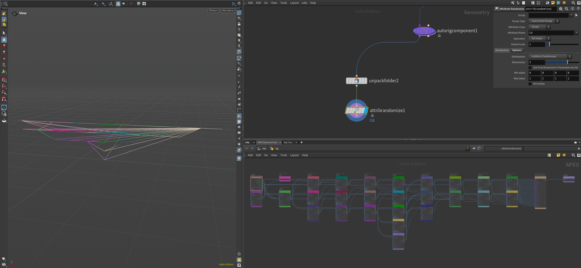
In future posts, I'll show what you can use this Network View for, but for now, just know that it exists.
Configure IK
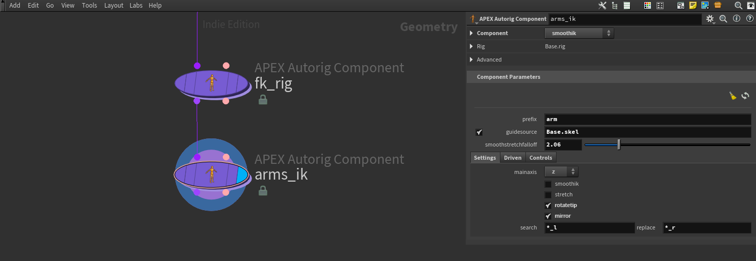
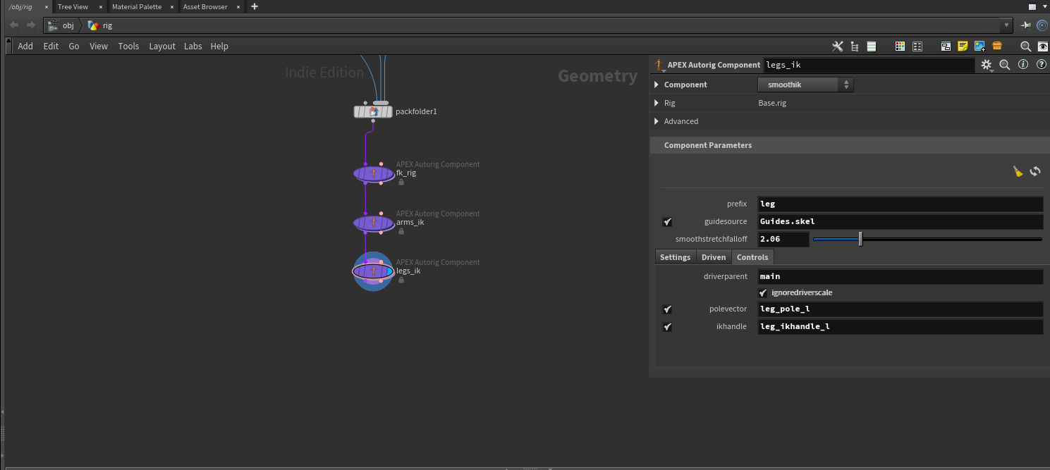
Moving on, let's set up an IK rig for the arms and legs respectively. The setup for this is very similar to setting up FK, you just need to use a different preset in the Autorig Component (smoothik). Please note that you need to set up FK before IK as some of the functionality is dependent on the properties added by the FK Autorig Component node.
When you've initialized the smoothik preset you'll get some new parameters to fill out. You'll need to set up the guidesource first which in our case should point to the guides.skel skeleton we set up. This is because we want to use the custom control joints we made for the IK portion of the rig. Also set a prefix (in our case we're starting with the arms so I've set it to arm).
Once you've done this you should configure what mainaxis your rig is using, whether or not you want it to stretch or not, and if you want to enable mirroring or not. Mirroring will grab all your left joints and mirror the ik setup to the right side based on the search parameters in the bottom.
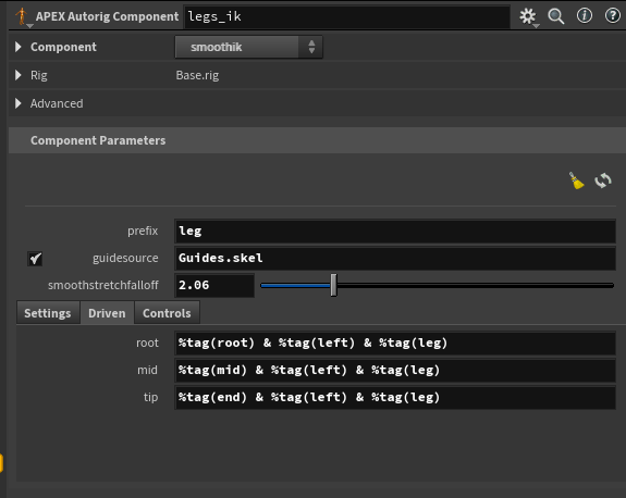
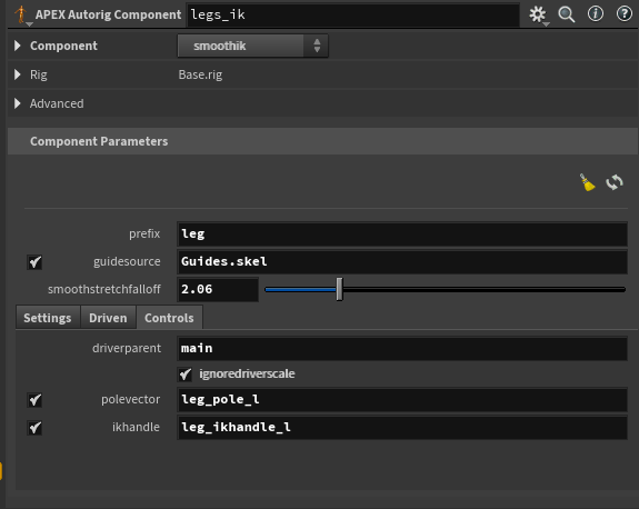
Aside from this you also need to set up your driven joints. You need to target the root, mid, and tip of your IK chain. I've done it below using tags again.
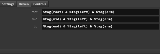
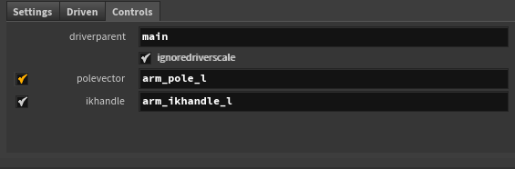
Finally, you need to set the driverparent (usually top of your guides.skel hierarchy - in my case called main) as well as your polevector and ikhandle. You must name these joints exactly like in your guide skeleton. Alternatively, you could also use tags again if you've set them up.
And voilà! You have IK arms set up for both sides of your rig.
To finish the IK portion of our rig we just need to do the same for the legs. Copy the Autorig Component node, adjust Driven joints to leg instead of arm and you got IK setup for your legs as well. See below for some examples:
Configure Spine
Lastly I'll cover how to setup the spine. This one is relatively simple as you need to configure just a couple parameters.
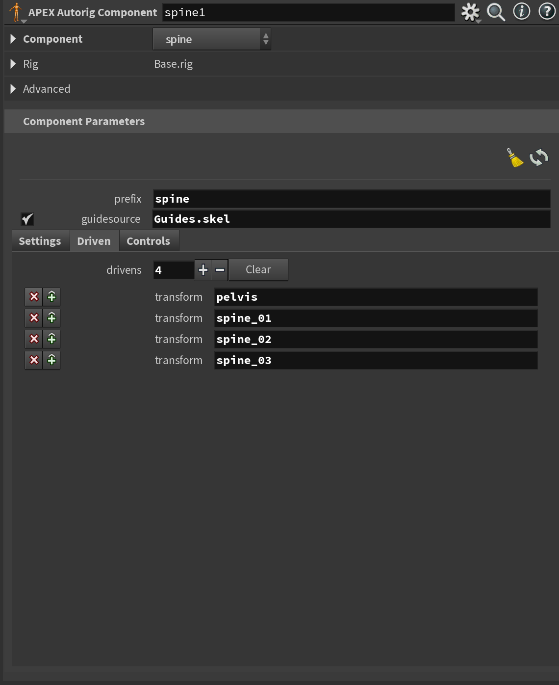
First, in the driven section you'll need to select each of your spine joints starting from the pelvis. This will initialize them all into the spine rig.
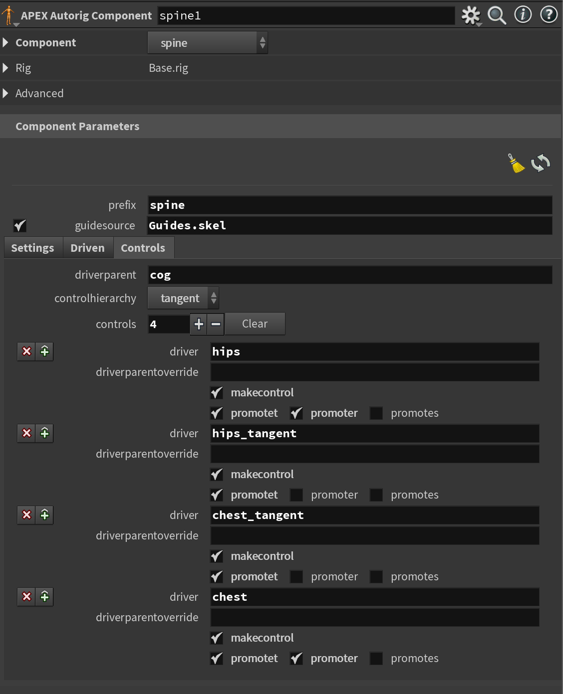
Then, in the Controls section, you'll need to pick the driverparent (in my case I picked my cog (center of gravity) control joint from my Guides.skel skeleton).
There is also a controlhierarchy option for you to look into. It determines the hierarchy of your spine and by extension its behavior. Mostly I would recommend just sticking with the tangent control hierarchy, but give the others a try too.
Lastly, you'll have to pick how many controls you want to generate on your spine. In general, I think the defaults work great for most cases, but you can in theory add as many as you'd like.
You'll notice that there are toggles for promotet, promoter, and promotes. These will allow you to choose if the user should be able to translate, rotate, and/or scale the created controls.
Deformation
Now that we have the core logic of our simple rig we just need the final parts - deformations and controls.
We'll start with Deformation. Earlier in this article I mentioned how to set up skinning on our mesh. Now we need to use that data so we can have a proper character to animate instead of a bunch of joints.
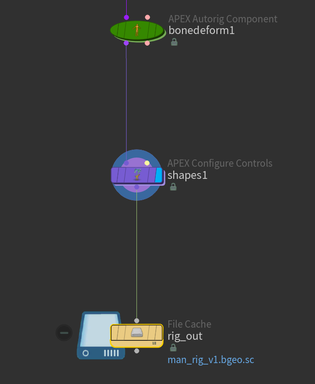
To set this up you need to add yet another Autorig Component - this time initializing it to bonedeform.
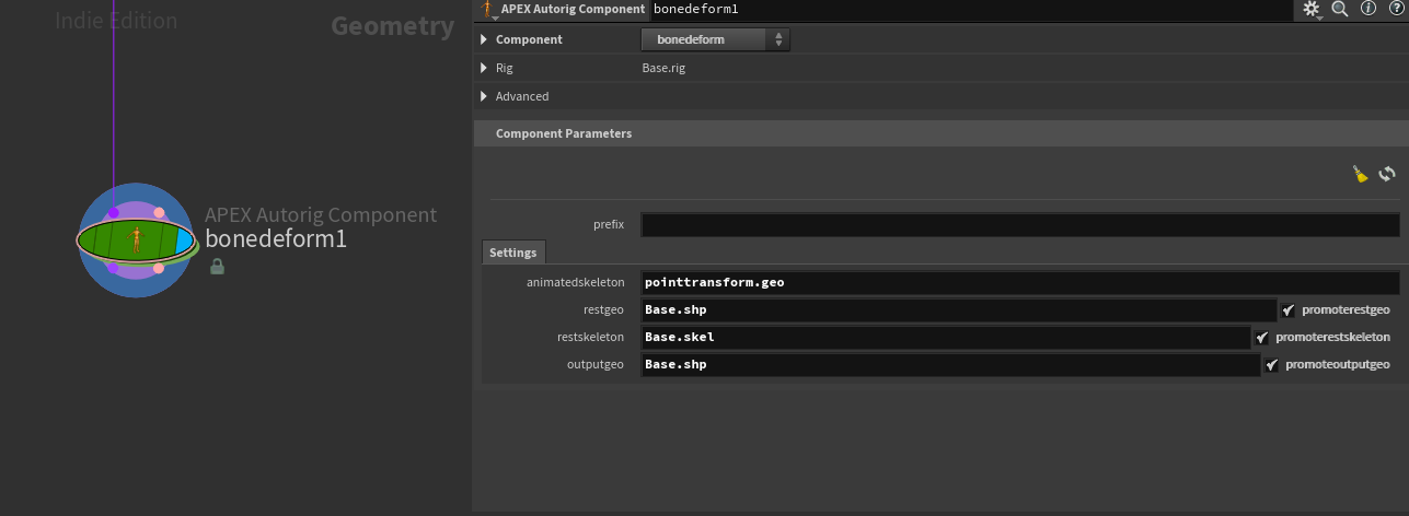
Here's a quick breakdown of the parameters - there are only a few but they're important to get right.
- animatedskeleton - this refers to the name of the node that outputs the final transforms of the joints in the APEX Network. If you've followed along here this will be pointtransform.geo - but I urge you to try and unpack the rig using an Unpack Folder and try to find this node.
- restgeo - name of mesh file in your character "folder"
- restskeleton - name of the skeleton in your character "folder"
- outputgeo - as it suggests, the name of the output mesh file in your character "folder". Should be the same as the restgeo.
And that's it, after setting up these parameters correctly we have our mesh following our joints.
Controls
We're almost there! Let's look at how to create controls.
Controls are nice and easy to set up. All you need is to drop down an APEX Configure Controls node and plug in the name of your skeleton "file" (usually Base.skel) in your Rig Source.
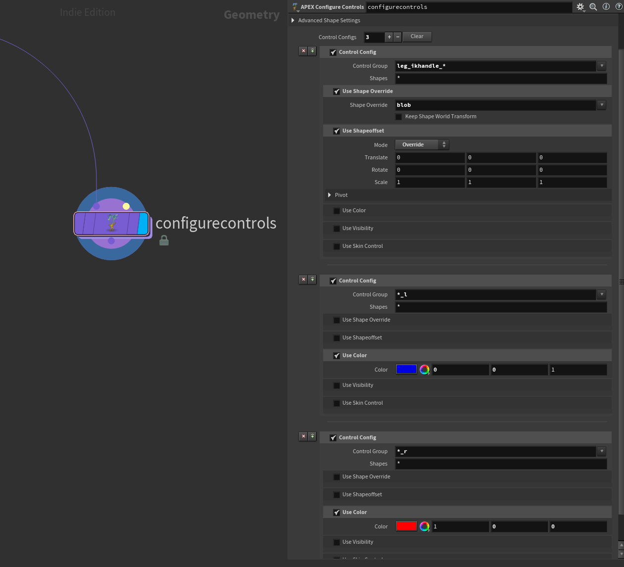
Then you simply add Control Configs and set up which shapes and colors you want to use for each group of joints. You plug in the name of your joint/control in the Control Group parameter (you can even use regex!) and pick whichever shape or color you want.
The neat thing about this node is that you can stack different configs. So you could color all the left controls with one config, and define the shapes with another. Lots of possibilities to have a very flexible setup. See the screenshot below for an example of this.
Packaging Rig and Animating
Great! We now have a working rig. But a rig won't be as useful unless there's a way for an animator to pick it up. Let's take a look at that now. The new APEX system has a very straightforward way of sharing your rigs and adding animation to them.
Packaging Rig
First, we need to package our rig so it's easy to share and load in other Houdini scenes. This couldn't be easier.
With APEX Rigs all you need to do is add a regular Geometry ROP or filecache at the end of your SOP network and save out your rig as a .bgeo or bgeo.sc.
You'll then be able to load this file to any scene that requires this character. Since the rig is exported in such a simple manner it also opens up some great opportunities to build small pipeline tools around it.
Animating
So how do we use our rig and save the animation? APEX introduces a new way of approaching this, luckily, like packaging the rig, it is also very straightforward. I've outlined the steps below:
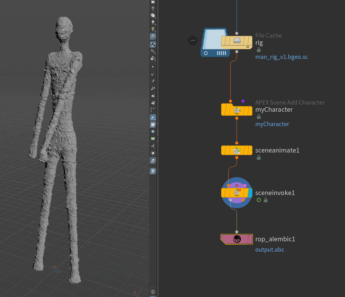
- Load your rig (usually through a File or File Cache node)
- Add an APEX Scene Add Character node - this is the node that adds your character to the scene
- Add an APEX Scene Animate - this is the node you'll be animating on
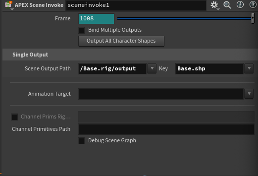
- When done animating, add an APEX Scene Invoke node. This will process the animation created in the Animate node so you can export it. All you need to do is set up the Scene Output Path and Key. The Scene Output Path should be set to the path of the output of your rig (default /Base.rig/output) and the key should be set to the "File" you want to export (default Base.shp).
- Export your animation any way you'd like.
All your animation happens in the APEX Scene Animate node - to use it you simply select the node and press enter while your cursor hovers over the viewport. When you use this node you enter a special state called the "Animate State" - you can read more about it here: https://www.sidefx.com/docs/houdini/character/kinefx/animatestate.html
Conclusion
That wraps up this little overview. I've only scratched the surface of what's possible with APEX and Autorigging, but I hope it gave you some insight to start exploring on your own. I hope to cover more APEX in the future so if you're interested feel free to subscribe below!
Let me know in the comments if there is anything you'd like to see expanded upon.
Thank you for reading!